

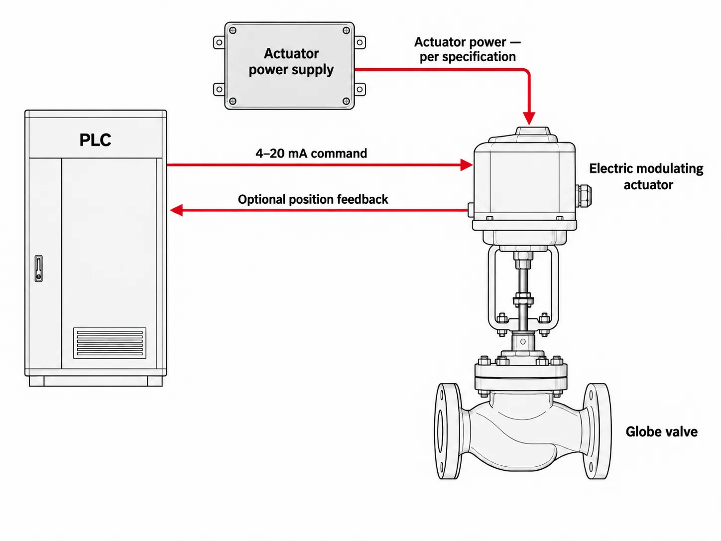
A 4–20 mA electric control valve uses an analog current signal to command a modulating electric actuator, which moves the valve toward a target position. A separate electrical supply powers the motor. Position feedback, when provided to the control system, reports measured position through its own output connection. These functions need separate specifications even when they are housed in one actuator.
The signal alone does not establish control performance. An electric on/off valve may provide 4–20 mA position feedback without accepting a proportional position command. A modulating package must also provide enough thrust or torque under load, tolerate the required adjustment frequency and respond consistently to small position changes. Its behavior on signal loss must be distinguished from its behavior on power loss.
Separate the Control Signal, Power Supply and Position Feedback
Read “4–20 mA” together with the connection’s function and direction. A command input carries the controller’s requested position to the actuator. A position output carries measured position back to the control system. The motor supply provides the energy for movement. Matching one connection does not establish compatibility with the other two.
| Connection | Function | Compatibility checks |
|---|---|---|
| Control input | Receives the target position | Signal range, direction, input burden and isolation |
| Motor power | Powers valve movement | Voltage, AC/DC, phase, frequency and current demand |
| Position output, if fitted | Reports measured position | Output range, loop supply, allowable load and scaling |
What the current signal represents
For a linear configuration set so increasing current opens the valve, the target travel percentage is calculated as (I − 4) ÷ 16 × 100, where I is the input current in milliamps. Under that configuration, 4 mA commands closed, 12 mA commands half travel and 20 mA commands fully open. Reverse action, split-range control or a configured signal characteristic changes that mapping.
The calculated percentage is a target, not a measurement. Actual travel depends on the actuator and valve reaching the commanded position. Flow then depends on the valve’s flow characteristic and operating pressure drop, so a 12 mA command does not generally mean half the maximum flow.
Loop power is different from motor power
A loop-powered input circuit can use energy from the current loop for its signal electronics. The electric motor still needs its specified power supply. This distinction matters when a wiring description refers to a two-wire signal connection: it does not mean the entire motorized valve operates from those two signal wires.
The command circuit also needs enough voltage to drive the required current through the actuator input, cable resistance and any isolators or barriers. Current signaling tolerates cable resistance only within that voltage budget. PR electronics explains this relationship in its current-loop fundamentals guide. Check the command and feedback circuits separately, including which device supplies each loop.
What position feedback can confirm
Internal position sensing allows the actuator’s positioning controller to compare demand with measured movement. A separate feedback output makes a position measurement available to the PLC or DCS. That output may be optional, and its range need not match the command input.
The sensor location determines what the feedback proves. An actuator output-shaft measurement may not reveal lost motion in a coupling or linkage downstream of the sensor. Open and closed limit contacts provide still less information: they indicate end positions rather than continuous travel. Neither position feedback nor a closed-limit signal establishes seat tightness or actual process flow.
Check That the Valve Package Is Built for Modulating Duty
A valve used for flow, pressure or temperature control must make intermediate movements as process demand changes. It needs more than the ability to stop between its end positions: the actuator must tolerate repeated corrections, and the valve must provide usable throttling behavior over the required operating range.
On/off versus modulating control
An on/off actuator normally moves the valve toward an open or closed limit in response to a discrete command. It may include continuous position feedback for monitoring, but that output does not establish that the actuator accepts a proportional position demand or is rated for frequent adjustment.
A modulating actuator compares the demanded position with its measured position and drives the valve to reduce the difference. Its motor, gearing and controls must support that operating pattern. Where a manufacturer offers a positioning module for an on/off actuator, compatibility and the resulting duty rating must be confirmed for that combination. Adding analog control electronics does not automatically establish unrestricted modulating capability.
The valve body also matters. A valve selected for isolation may have a flow characteristic, seat design or allowable throttling range that does not suit the process. For example, a small angular movement near closure can produce a substantial flow change in some rotary valves. Accurate actuator positioning cannot compensate for a valve whose usable flow range does not match the duty.
Power, duty cycle and control frequency
Compare the expected movement pattern with the actuator’s documented operating limits. Motor running time, starts and direction reversals describe different demands. A valve making frequent short corrections may have little accumulated running time while repeatedly starting and reversing its drive. A permitted running-time percentage alone does not establish that this pattern is acceptable.
Load and ambient temperature affect the assessment. The actuator must remain within its specified duty limits while producing the required output under the installation conditions. Thermal protection may stop an overloaded or overheated motor, leaving the valve unable to follow the controller even though the command signal remains valid.
Persistent hunting should be investigated rather than treated as normal evidence of responsive control. Signal noise, friction, backlash or loop tuning can cause repeated corrections. Increasing deadband may reduce motor activity, but it also increases the change in demand needed to trigger movement. That trade-off must remain compatible with the process’s control needs.
Check the utility supply during movement as well. An electric actuator needs adequate voltage at its terminals under the relevant current demand. A pneumatic alternative needs sufficient air pressure and delivery capacity while stroking; an acceptable static gauge reading alone does not demonstrate this. A pneumatic valve fitted with a 4–20 mA positioner still uses compressed air to produce valve movement.
Electric actuators vary considerably in speed and modulating capability. Compare the selected design’s duty and response data with the required operating pattern instead of assuming that all electric actuators are slow or that every analog-input actuator supports continuous adjustment.
Match Actuator Thrust or Torque to the Valve Load
The actuator must move and seat the valve under the most demanding applicable operating condition. Normal flow, initial opening and final closure can impose different loads. A valve that moves freely during an unpressurized test may stall or fail to seat once differential pressure and friction act on the assembly.
Linear thrust inputs
For a sliding-stem control valve, pressure force depends on the pressure difference acting across the trim and its effective unbalanced area. That area comes from the valve’s construction; nominal pipe area is not an adequate substitute. Pressure-balanced trim reduces the unbalanced load, but residual pressure forces and seal friction still require consideration.
The thrust assessment must account for:
- Pressure conditions and flow direction: these determine whether fluid forces assist or oppose movement in each operating state.
- Seating and unseating requirements: final closure and initial opening may require more force than movement through the middle of the stroke.
- Packing, guide and seal friction: these loads depend on construction, adjustment, temperature and condition.
- Travel and additional mechanical loads: the actuator must provide the required stroke and accommodate any relevant spring, stem-weight or construction-specific forces.
Evaluate these forces in the appropriate direction and operating state rather than adding unrelated maximum values. Maximum shutoff differential deserves a separate check: when flow stops, the pressure distribution may differ substantially from normal regulating conditions. The resulting requirement must be compared with available actuator thrust under the specified supply, speed and duty conditions.
Rotary torque through travel
For a ball, segmented-ball or butterfly control valve, use the valve’s torque requirements across its operating angle. Breakaway torque describes the effort needed to start movement; running torque describes movement through travel; seating or unseating torque covers interaction with the seat. The highest requirement is not necessarily at the same position for every valve design.
Differential pressure, flow direction, seat material, temperature and time spent stationary can change these loads. Fluid forces during throttling can also produce significant dynamic torque. A nominal actuator torque rating should therefore be checked against the applicable valve torque curve or sizing data, including the manufacturer’s stated conditions and selection margin. The actuator selection guide covers this matching process.
Mechanical limits and protective settings
Available output must be sufficient without exceeding the allowable loads of the valve stem or shaft, coupling, bracket and drive components. Increasing actuator size can introduce a damage risk if its output and protective settings are not coordinated with those limits. Torque or thrust protection must allow the required operating load while protecting the assembly.
Confirm the required stroke or rotation, mounting alignment and specified seating method as part of the same review. If movement on power loss is required, check the output available from the fail-safe mechanism or stored-energy arrangement separately from normal powered operation. Passing the normal-load calculation does not establish that the valve can complete its failure action.
Evaluate Positioning Accuracy on the Assembled Valve
A small change in the 4–20 mA command is useful only if it produces a sufficiently small, repeatable valve movement. An actuator’s resolution describes one part of that response. It does not establish the positioning accuracy of the complete valve, coupling and actuator assembly under load.
Read each performance term separately
Resolution describes the smallest increment the device can distinguish or produce, depending on the manufacturer’s definition. Positioning accuracy describes how closely measured position agrees with the required position under stated conditions. A fine command resolution can coexist with a larger positioning error.
Repeatability concerns how consistently the assembly returns to a position during repeated tests under the same conditions. Hysteresis concerns the difference in position at the same command when approached from opposite directions. Deadband describes a range of input change that produces no detectable output movement, particularly after a reversal. Hysteresis is not simply another name for response delay.
Compare specifications only when their measurement basis is clear. A percentage of full travel, an angular error and a percentage of the commanded value describe different limits. Test load, movement direction and the location of the position sensor also affect what a published figure establishes.
Check where movement is measured
Gear backlash or clearance in a coupling can allow part of the drive to move before the valve stem or shaft follows. Packing friction can hold the valve stationary until sufficient force develops, followed by a sudden movement. These effects can make small corrections inconsistent even when larger movements appear satisfactory.
A feedback sensor near the motor may not detect lost motion farther along the drive train. A sensor on the actuator output measures more of that chain, but it may still miss movement lost between the actuator and valve. Where assembly performance is being assessed, the test should identify the measurement point and, where needed, measure valve travel independently.
Use small steps and reversals to assess response
A full-stroke test can confirm travel and reveal gross operating problems. Small command steps at relevant operating positions reveal whether the assembly responds to normal regulating corrections. Tests in both directions help distinguish repeatable positioning from reversal-related lost motion.
The response record should show the applied command and measured travel against time. Read the initial delay, movement toward the target, overshoot and settling separately. A fast initial movement is not enough if the valve continues oscillating or settles outside the required position tolerance.
Keep the test conditions beside the result, including supply, load, position and control settings. An unloaded actuator test cannot by itself establish performance against process forces. Even verified valve positioning remains distinct from flow-control accuracy, which also depends on valve sizing, flow characteristics, pressure changes, measurement and loop tuning.
Define Signal-Loss and Power-Loss Actions Separately
A fail-position requirement needs both a triggering event and a required valve position. “Fail closed” is incomplete if it does not identify whether closure must occur after loss of the command signal, loss of motor power or both. The same electric actuator can behave differently in each event because the energy available for movement changes.
| Failure event | Possible behavior | What must be verified |
|---|---|---|
| Command lost; motor power available | Stop or move to a configured position | Detection threshold, delay and configured action |
| Motor power lost | Stop, hold or move using a fail-safe mechanism | Holding capability or available return energy under load |
| Command and motor power lost | Depends on the complete failure arrangement | Control priority and behavior with both supplies absent |
| Power restored | Resume control or remain inhibited | Restart logic, valid command and energy-storage readiness |
Loss of the command signal
With power available, the actuator’s controls may detect an out-of-range input and initiate a configured action. The detection threshold and delay are device-specific. A valid command at the bottom of the configured range must not be confused with a broken signal circuit.
Signal monitoring also has limits. If a controller fault leaves the output frozen at a valid current, a basic out-of-range detector may see a legitimate command. Detecting that condition requires diagnostics beyond simply checking whether current is present.
Loss of motor power
A programmed movement cannot occur without an available energy source. Spring-return mechanisms or suitable stored-energy systems can provide movement after the normal supply disappears, but their output must cover the valve load throughout the required travel. Battery condition, capacitor charge or other readiness requirements depend on the design.
Stopping the motor does not necessarily guarantee that the valve holds its position against process forces. A specified hold action requires suitable resistance to back-driving or a holding mechanism. Its capability must be assessed against the applied load, rather than inferred from the valve remaining stationary during an unloaded power-off test.
Failure action belongs to the complete assembly
The required position follows the process consequence of losing control. It cannot be determined from the signal direction or a “normally closed” label alone. Local stop settings, interlocks, protective trips and emergency commands may also affect movement, according to the actuator’s documented control priorities.
Use the fail-position guide to distinguish the required failure events, then verify each event separately on the configured assembly under defined test conditions. Record the starting position, available supply or stored energy, valve load, movement time and final position. Reaching the closed position confirms movement; any required seat-tightness claim needs its own applicable leakage evidence.
Verify the Complete Package with Drawings and Response Records
Drawings establish how the valve package is configured. Test records show what it did under particular conditions. Both are needed to connect an electrical specification with actual valve movement, and each document must correspond to the assembly being evaluated.
Use the wiring drawing to trace each function
The configuration-specific wiring diagram should distinguish motor power, command input, position output and discrete status contacts. Trace each connection to the corresponding controller channel or supply. Check polarity, loop-power arrangements and isolation against the equipment documentation rather than assuming that identical signal ranges mean identical wiring.
A published example is the wiring diagram in the Valworx DPS instruction document. It separates power, positioning signals and confirmation switches. The document also distinguishes its configured signal-loss action from its external-power-loss action. Those connections and settings apply to the documented equipment; they are not a terminal guide for other electric actuators.
For a pneumatic alternative, the pneumatic accessory selection guide explains how the positioner, solenoid and air supply interact.
The mechanical assembly drawing answers different questions: required travel, actuator orientation, coupling arrangement, mounting interfaces and clearance. An outline drawing can establish the arrangement, but it cannot prove positioning accuracy or available thrust under load.

Read a response curve with its test conditions
A useful response curve plots the applied demand and measured position against the same time reference. It should identify the step size, starting position, movement direction, measurement point and operating conditions. Without these details, a response-time figure cannot be reliably compared with another assembly’s result.
The official Rotork CVA brochure provides a manufacturer-published step-response example and describes a self-test routine that evaluates quantities including deadtime, response time, settling time and force. It illustrates the distinction between reaching a position and responding dynamically. It is a third-party actuator example, not a MacoTango assembly test or a universal acceptance target.
For the proposed valve package, examine both forward and reverse movements at relevant operating positions. A curve from one direction or one unloaded position cannot establish performance throughout the valve’s operating envelope.
Connect the test result to the supplied assembly
A traceable functional record identifies the valve and actuator configuration, drawing revision, control settings, test supply, applied load, measurement instruments and acceptance criteria. It records the command, independently measured travel where required, feedback output and timing. Signal-loss, power-loss and restoration checks need their own recorded conditions and results.
Interpret a passing result within that boundary. An unloaded positioning test supports unloaded positioning performance. A loaded movement test supports operation at the documented load. A seat-leakage test addresses shutoff under its specified conditions. None of these results automatically proves the others, and a blank test form is not evidence that an assembly passed.
Confirm the Selected Actuator’s Input and Position Output
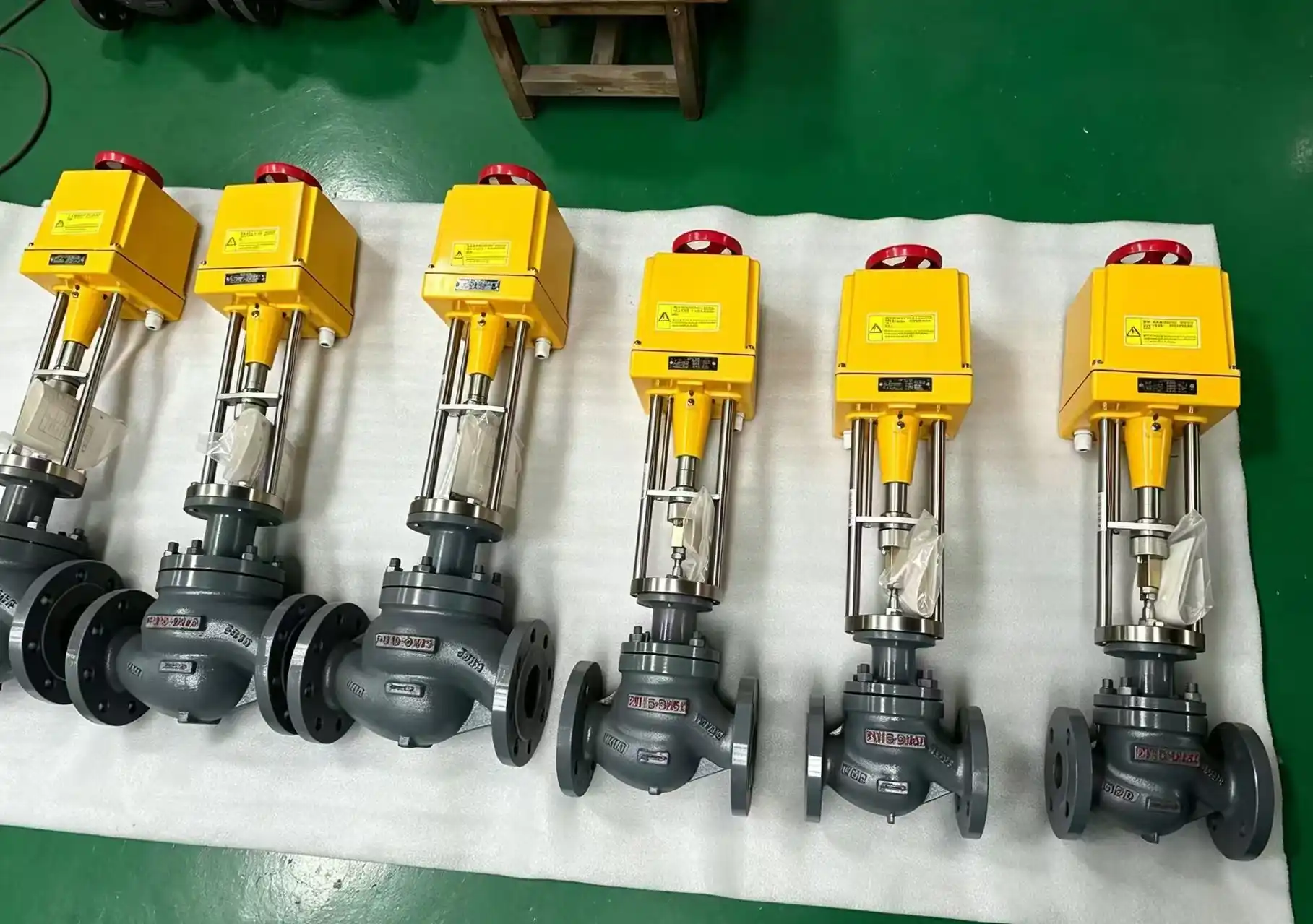
The MacoTango selection manual documents a modulating electric actuator arrangement with a 4–20 mA setpoint input and a separate 4–20 mA position-feedback output. This is a documented actuator arrangement, not a statement that every electric valve or actuator includes both interfaces.
For the proposed package, the selected actuator datasheet must identify those functions separately. Its wiring drawing must then show the corresponding connections, loop supply and isolation. The valve brochure identifies the valve construction; it does not establish the electrical options of an actuator selected later.
| Document field | What it resolves |
|---|---|
| Actuator identification and revision | Which actuator and control version the interface data applies to. |
| Demand input | Signal or protocol, input burden and direction of increasing command. |
| Position output and option code | Whether continuous feedback is included, what it measures and the output circuit requirements. |
| Power and failure settings | Motor supply plus separate responses to signal loss and power loss. |
| Drawing and verification record | Connections, controller channels and the conditions under which command and feedback were checked. |
Use the electric globe control valve ordering information to define the electrical configuration with the valve duty. The position feedback requirements also explain why continuous travel, limit contacts and digital communication provide different information.
Select for the Control Duty, Not the Signal Alone
A suitable 4–20 mA electric control valve combines compatible electrical interfaces with a valve and actuator built for the required modulation. Its available thrust or torque must cover the operating load, while its duty rating and assembled response must support the expected corrections. Signal-loss and power-loss behavior require separate verification. Base the final selection on configuration-specific drawings and relevant test records: a matching signal range establishes an interface, but dependable regulation requires the complete assembly to perform under the intended conditions.