

A globe control valve uses linear stem motion to move a plug relative to a seat, changing the flow area through the valve. In modulating service, an actuator adjusts and holds the plug at intermediate positions in response to a control signal. This allows the valve to regulate flow within a pressure, temperature, level, or flow control loop.
Globe construction offers several ways to shape the flow response through the plug, seat, and cage design. Its suitability depends on how that trim works with the available pressure drop and actuator thrust. An oversized trim can leave normal operation close to the seat, while insufficient thrust can prevent the valve from reaching its commanded position or closing properly.
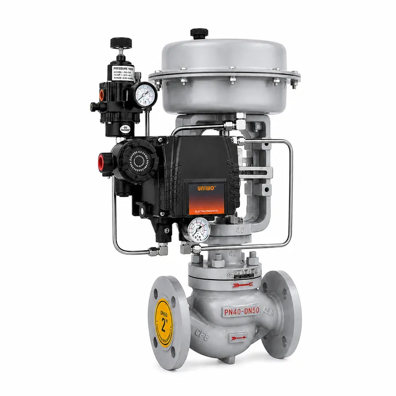
What is a globe control valve?
The term “globe” describes the valve’s construction, while “control” describes its duty. A manual globe valve can throttle flow at a handwheel-set opening, but it cannot adjust that opening automatically as process conditions change.
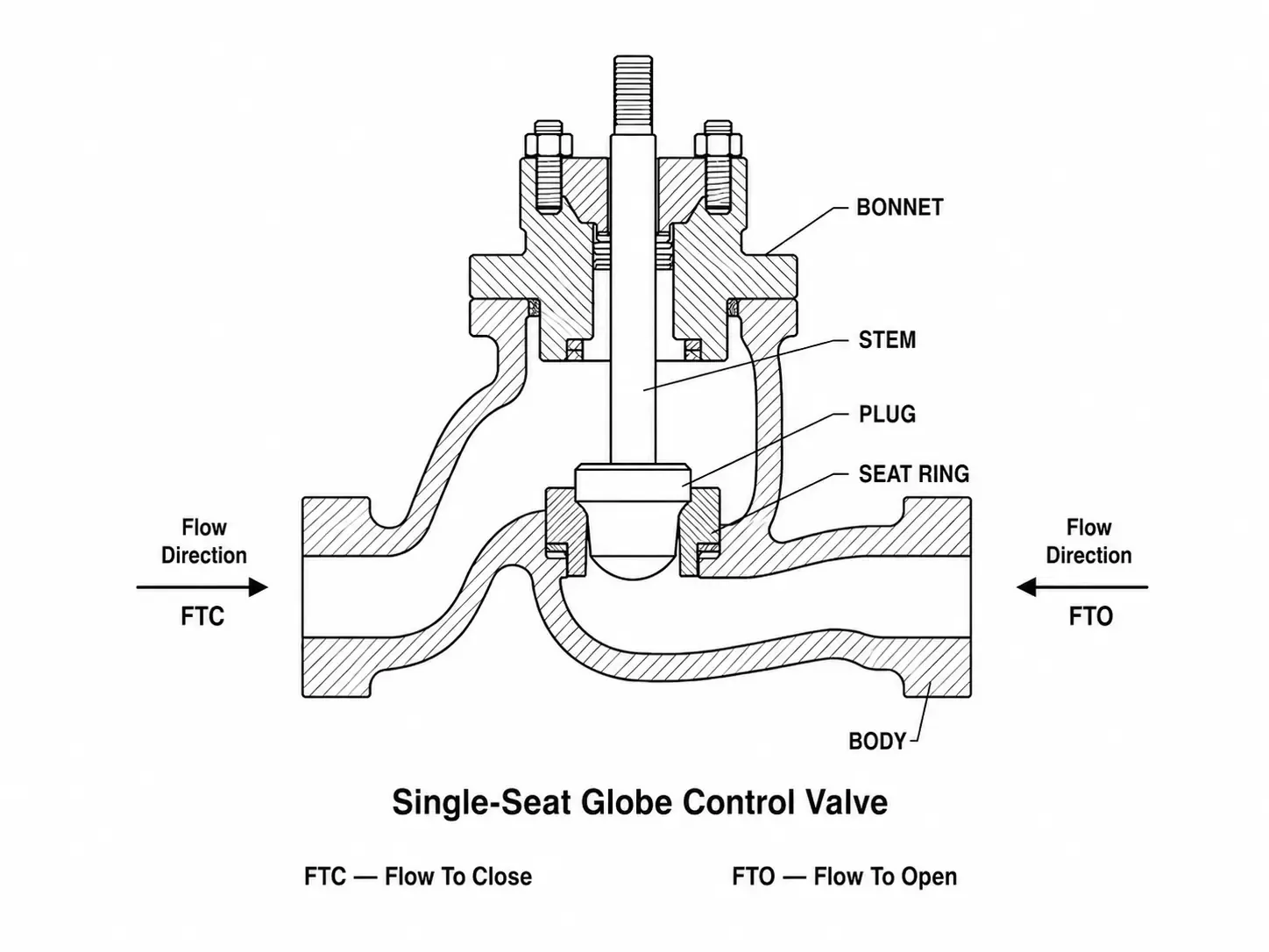
Adding an actuator allows automatic movement, although the assembly may still be configured for on/off service only. For modulating control, the trim must suit sustained throttling, and the actuator must position the plug throughout a usable stroke under process load.
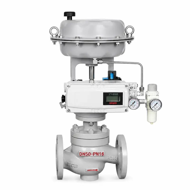
A valve positioner can improve travel control by comparing the requested position with actual stem position and adjusting the actuator output. It controls valve position; a separate process measurement tells the controller whether the required flow, pressure, temperature, or level has been reached. Reaching the commanded valve position therefore does not, by itself, confirm that the process is at its setpoint.
How does a globe control valve work?
A globe control valve regulates flow by changing the restriction between its inlet and outlet. The actuator moves the stem and plug, while the trim geometry determines how the available flow area changes through the stroke.
Signal and stem movement
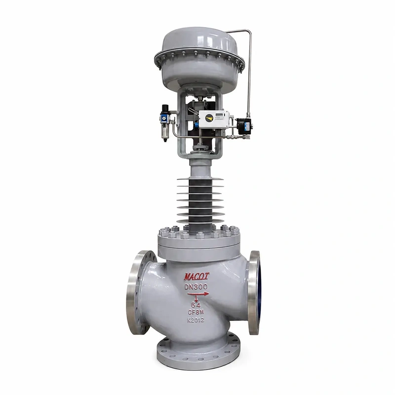
The controller sends a command to the actuator or its positioner. A pneumatic actuator converts air pressure into stem thrust; an electric actuator uses a motor and drive mechanism to produce linear movement. The stem transfers that movement to the plug inside the valve body.
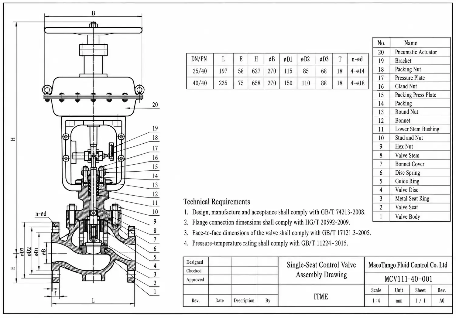 Example of a pneumatic globe control valve assembly with a positioner. Component arrangement varies by design.
To reach and hold the requested position, the actuator must overcome the forces acting on the assembly. These include pressure forces on the plug and friction from the packing and guides. Packing seals around the moving stem, while guides keep the plug aligned. Excessive friction or inadequate actuator thrust can prevent a command change from producing the intended travel.
Plug, seat and flow path
As the plug moves away from its closed position, it opens a passage through the trim. Moving it toward the seat reduces that passage. At closure, the plug contacts the seating surface, and the applied seat load helps establish the specified shutoff performance.
In a contoured-plug design, the plug profile shapes the opening as the stem travels. In some cage-style designs, plug movement exposes or covers openings in the cage. A cage may also guide the plug or retain the seat ring, so its function must be identified from the actual construction.
Fluid passes through this restriction and into the downstream passage. The resulting flow depends on both the opening and the pressure conditions across it. Holding the stem at one position therefore does not guarantee a constant flow rate if the inlet or outlet pressure changes.
Which globe control valve types matter?
Globe control valves are classified by body arrangement, trim construction, and actuator type. These descriptions can overlap: one valve may have a straight-pattern body, a single seat, a pressure-balanced plug, and pneumatic actuation. Each label answers a different selection question.
Body patterns and two-way or three-way service
The three commonly named globe valve body patterns are T- or Z-pattern, Y-pattern, and angle. A conventional straight-pattern body has inlet and outlet connections on the same pipeline axis, with the fluid changing direction internally around the seat. A Y-pattern design inclines the stem and seat arrangement to provide a more direct passage. An angle body places the inlet and outlet perpendicular to each other, combining the valve with a change in piping direction.
Body shape affects the flow path and installation layout, but it does not establish capacity or severe-service suitability by itself. The selected trim still determines the throttling passages and much of the pressure-reduction behavior.
Two-way valves regulate flow through one inlet and one outlet. Three-way globe valves combine streams in mixing service or split a stream in diverting service. Mixing and diverting arrangements require the correct port connections and internal construction; they should not be assumed interchangeable.
Single-seat, cage-guided and balanced trim
Single-seat describes the main plug-to-seat shutoff interface. In an unbalanced design, differential pressure creates a net force on the plug that the actuator must overcome. As the effective loaded area or differential pressure increases, that force can become a major part of the actuator requirement.
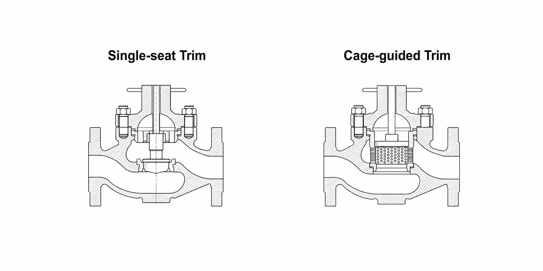
A pressure-balanced design exposes opposing effective areas to pressure to reduce the net fluid force. It can reduce the required actuator thrust, but the actuator must still overcome friction and provide the necessary seat load. Balance seals also introduce additional sealing requirements that affect shutoff performance.
Cage-guided describes how the plug is supported during travel. A cage-guided valve can also be single-seated and pressure-balanced. Cage guidance alone does not establish pressure balance, noise reduction, or anti-cavitation capability; those functions depend on the specific passages, seals, and pressure-reduction stages.
Pneumatic and electric actuation
Pneumatic actuation uses instrument air and may suit frequent modulation where adequate air pressure and delivery capacity are available. Electric actuation uses a motor and may suit installations without instrument air. Either option must meet the required thrust, positioning response, and modulating duty.
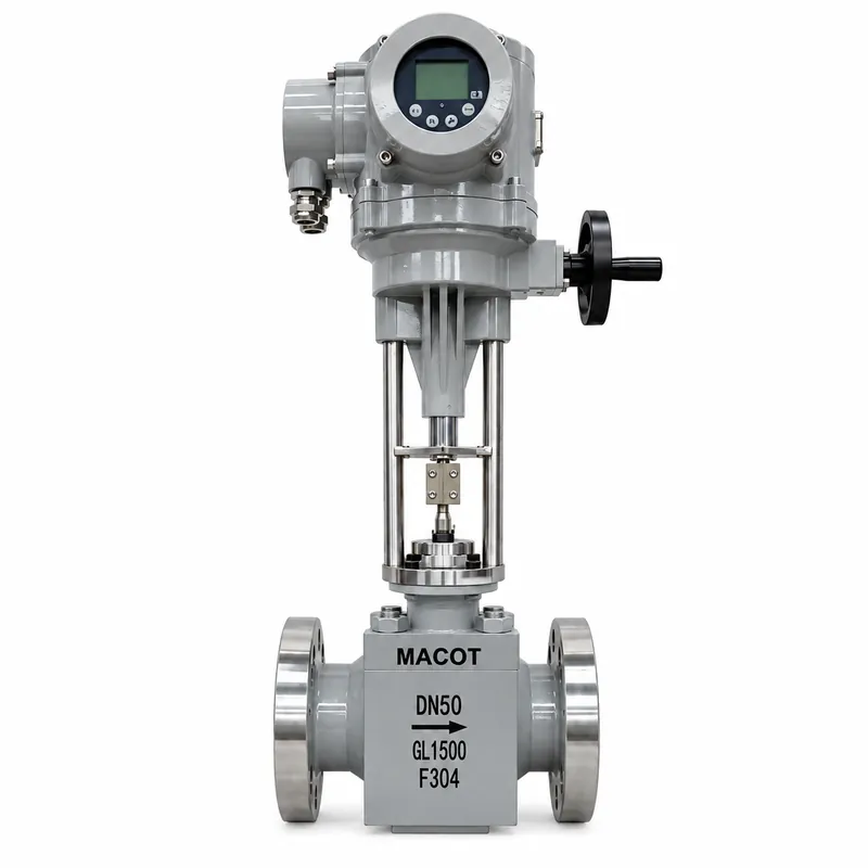
The energy source does not determine the valve’s flow characteristic or guarantee a particular failure position. The complete actuator and accessory arrangement must provide the required response to loss of air, power, or control signal.
Why valve travel does not equal flow rate
Linear stem movement does not necessarily produce a linear change in flow. The result depends on the trim characteristic and the pressure drop across the valve.
Linear and equal-percentage trim
The inherent flow characteristic describes how capacity changes with valve travel at a constant differential pressure:
- Linear trim: Equal increments of travel produce equal increments of capacity.
- Equal-percentage trim: Equal increments of travel produce the same percentage increase in the existing capacity. The absolute increase becomes larger as the valve opens.

The piping system changes the response
In service, piping and equipment share the available pressure difference with the valve. As flow, pump operation, or supply conditions change, the differential pressure across the valve can also change.
The installed flow characteristic therefore reflects both the trim and the system. Equal-percentage trim can produce a more nearly linear installed response in some systems, but this depends on how the available valve pressure drop changes with flow. The linear versus equal-percentage selection guide explains how to compare the two characteristics under changing system conditions.
Excess capacity can reduce usable travel
An oversized trim may pass normal flow close to the seat, leaving little travel for adjustment at lower flows. Friction and small position errors can then have a greater effect on control. A positioner can improve travel accuracy, but it cannot change the trim’s capacity curve.
Check minimum, normal, and maximum flow against the configured valve’s capacity-versus-travel data, using the pressure conditions at each point. Passing maximum flow alone does not establish controllability across the operating range. The control valve sizing guide explains how to evaluate these operating cases before selecting body and trim capacity.
When should you use a globe control valve?
A globe control valve is a strong candidate when its trim options provide useful control over the required operating range. Typical duties include steam admission to a heat exchanger, cooling-water regulation, and process-liquid or gas flow control. In each case, suitability depends on the actual pressure conditions, fluid properties, and required response.
For steam heating, the valve adjusts steam flow as heat demand changes, so it must handle both reduced demand and peak load without unacceptable noise or capacity limits. In a cooling-water circuit, the available differential pressure may change with pump operation and other users on the network. These duties benefit from matching the trim characteristic to the system rather than choosing a valve solely by line size.
| Duty or constraint | Where globe construction can help | When to compare alternatives |
|---|---|---|
| Continuous modulation | Trim capacity and characteristic can be matched to the operating range. | A suitable rotary control valve meets the response with a smaller assembly. |
| Substantial pressure reduction | Specialized trim can distribute pressure reduction or attenuate noise. | The selected design cannot meet noise, velocity, or cavitation limits. |
| High flow with little available pressure drop | Suitable only if the configured valve provides sufficient capacity. | A higher-capacity rotary design better fits the pressure budget. |
| Fibers, crystals, or suspended solids | Suitability depends on passage size, guiding clearances, and wear exposure. | A more open flow path reduces plugging or deposit accumulation. |
| Mixing or diverting | A purpose-designed three-way valve controls the connected flow paths. | The branches require independent control or isolation. |
Where capacity, pressure loss, space, or solids handling drives the choice, the comparison of linear and rotary control valves provides a broader screening of alternative constructions.
For simple on/off isolation, the adjustable trim of a globe control valve may offer little benefit. A dedicated isolation valve may better meet the pressure-loss and shutoff requirements. Where both modulation and maintenance isolation are needed, treat them as separate functions rather than assuming the control valve’s closed position satisfies both.
What can limit performance in service?
A globe valve can provide enough flow capacity yet struggle to control or close under actual operating conditions. The pressure profile through the trim, available actuator thrust, and condition of the internal passages can each limit the usable performance of the assembly.
Pressure drop and unsuitable trim
In liquid service, pressure falls as fluid accelerates through the restriction and then partly recovers downstream. If the local pressure falls below the liquid’s vapor pressure, vapor bubbles can form. Their collapse during pressure recovery causes cavitation. If downstream pressure remains below the vapor pressure at the flowing temperature, vapor persists as flashing flow.
These conditions need different responses. Suitable pressure-staging trim can limit cavitation within its design envelope. Persistent flashing also requires attention to outlet geometry, velocity, and erosion exposure because pressure staging alone cannot make the downstream fluid remain liquid. A standard cage or a harder seating surface does not establish that either duty is covered. The guide to flashing and cavitation mitigation explains why pressure recovery and the location of damage change the remedy.
Gas and steam service can encounter choked flow and excessive aerodynamic noise. A general-purpose trim may provide the calculated capacity while failing the application’s acoustic or mechanical requirements. Noise alone, however, does not identify the mechanism; fluid state and operating pressures are needed to distinguish the cause.
Insufficient thrust or incomplete shutoff
The highest actuator load may occur during shutoff, when flow has stopped but the pressure difference across the plug is greater than during normal operation. An assembly that strokes freely without process pressure may therefore stall or stop short under load. For air-operated assemblies, the pneumatic actuator sizing guide covers linear stem thrust, minimum available air pressure, and shutoff load.
Closing performance also depends on the plug reaching the seat and applying the required load. Debris, damaged seating surfaces, excessive packing friction, or an incorrect travel setting can prevent this. A closed-position indication alone does not prove that the specified shutoff performance has been achieved, and leakage does not automatically mean the seat needs replacement. The control valve spare-parts guide explains how to separate wear evidence from faults that replacement parts cannot correct.
Solids and restricted passages
Fine cage openings, balance passages, and close guide clearances can collect particles or deposits. Restricted passages reduce capacity, while deposits around the guides can increase friction and disrupt plug movement. Material trapped at the seating surface can also prevent closure.
This creates a selection trade-off: trim that manages pressure reduction effectively in clean fluid may be unsuitable for a stream containing fibers or crystals. Passage geometry and the expected deposits must be considered together. Changing the body alloy alone will not resolve a plugging problem caused by narrow internal passages.
Choosing globe construction for the right duty
Globe construction is a good fit when its trim options provide the required modulation within the system’s pressure and flow limits. The selected assembly must provide both usable control travel and enough actuator thrust under operating and shutoff conditions. Where limited pressure availability or plugging risk becomes the deciding constraint, compare a suitable alternative flow path before committing to a globe valve. Body style identifies the starting point; the configured trim and its behavior in the installed system determine whether it fits the duty.