

Lug and wafer describe how a butterfly valve attaches to the pipe flanges. A lug body commonly accepts separate bolts from each side; a wafer body is clamped between the flanges by through-bolting. This changes connection and removal planning, but does not by itself establish pressure rating, temperature range, leakage or flow loss.
For installers and OEM skid builders, the first checks are flange compatibility, disc clearance and whether one flange will ever be removed. A lug connection does not automatically authorize dead-end pressure service or work on a pressurized joint.
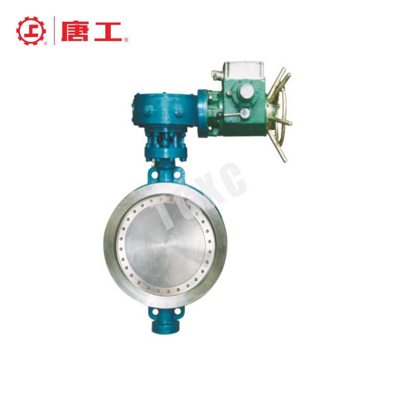
How Lug and Wafer Connections Differ
Lug Butterfly Valves
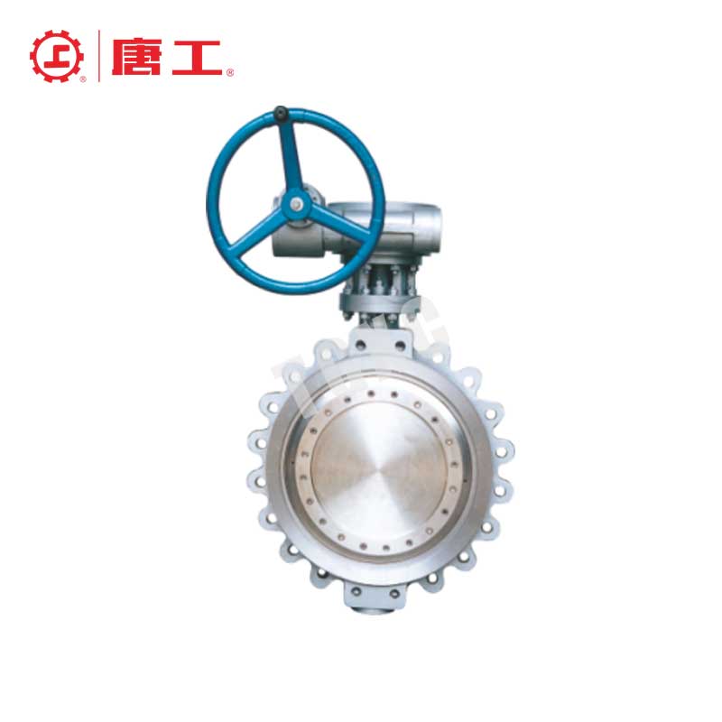
Threaded lugs around the body allow the two flange connections to use separate bolt sets. The thread may be machined directly into the lug or provided by an insert, depending on construction. One flange can remain attached while the other piping section is disconnected under an approved isolation procedure.
That mechanical arrangement is useful where a spool or downstream item must be removed. It does not mean the valve itself can be removed while it is still retaining pressure. The remaining flange, lugs, seat and support must all be suitable for the proposed condition.
Wafer Butterfly Valves
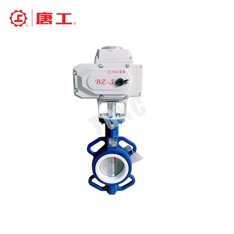
A wafer valve normally sits between two flanges, with studs or bolts spanning the assembly. Some designs have locating holes or tabs, but these should not be mistaken for a complete independent pressure-retaining connection. Centering still needs to be checked before final tightening.
The compact body may save weight and space. Wafer construction is not restricted to a universal low-pressure or low-temperature range: the complete valve design and materials establish its limits. For comparable internal geometry, the absence of threaded lugs does not establish a lower pressure drop.
Lug vs Wafer: What Actually Changes?
| Check | Lug arrangement | Wafer arrangement |
|---|---|---|
| Flange connection | Separate bolt sets; verify thread, engagement and length | Through-bolting; verify length across the complete joint |
| One flange removed | Possible only within the specified dead-end arrangement and limits | Do not assume pressure retention without the required mating flange |
| Pressure and temperature | Use the selected construction’s limits | Use the selected construction’s limits |
| Shutoff and flow loss | Seat, disc and internal flow geometry determine performance | Seat, disc and internal flow geometry determine performance |
| Installation envelope | Check lug clearance, bolt access, support and operator space | Check centering, stud clearance, support and operator space |
| Maintenance | Independent attachment can help spool-removal planning | Opening the clamped joint affects valve restraint and sealing |
Dead-End Service Needs a Separate Rating
Dead-end service here means pressure retained on one side with the other pipe flange removed. The lugged body must be explicitly approved for that arrangement. Its allowed pressure may be lower than the rating between two flanges, and can depend on size, disc, seat, temperature and pressure direction.
For example, Bray’s Series 30/31 specification lists separate between-flange and dead-end conditions for its lug design. That is evidence that the two conditions need separate checks; those values are not MacoTango ratings.
- Confirm the exact valve configuration and whether a downstream flange is required for the claimed rating.
- Obtain the permitted dead-end differential, temperature and pressure direction, with the required bolts and thread engagement.
- Check pipe and valve support after the adjoining spool is removed; do not transfer unsupported pipe loads into the valve.
- Apply the site’s isolation, locking, draining and zero-pressure verification procedure before opening a joint. Evaluate trapped fluid and stored actuator energy.
- Use the project’s approved positive-isolation arrangement where required. A shut butterfly valve or an optional blind is not, by itself, a complete work-isolation plan.
Installation Compatibility Before Tightening
Use the selected valve drawing and installation manual rather than a generic nominal-size chart. The open disc can project beyond the body faces. A heavy-wall pipe, lining, reducer, check valve or undersized gasket bore can obstruct it even when the flanges bolt together.
| Dimension or component | Confirm before assembly | What a mismatch can cause |
|---|---|---|
| Flange drilling and facing | Specified flange standard, size, class, hole pattern and mating face | Poor alignment or an unsupported connection |
| Face-to-face and gasket stack | Actual valve length and the specified seal arrangement | Incorrect compression or an installation gap mismatch |
| Pipe and gasket bore | Minimum clear opening around the disc sweep | Disc contact and damaged sealing surfaces |
| Lug bolts | Thread form, engagement, usable depth and bolt length on each side | Bottoming, inadequate engagement or lug damage |
| Wafer studs | Length through flanges, valve, washers and required engagement | Insufficient engagement or interference |
| Access and support | Actuator envelope, bolt/tool access and spool-removal space | A connection that cannot be serviced as planned |
Gasket requirements depend on the seat and flange design. Some resilient seats seal directly against the mating flange; other constructions require separate gaskets. Bray’s resilient-seat installation manual gives model-specific examples of disc clearance and flange sealing. Follow the instructions for the supplied valve instead of adopting one gasket rule for every butterfly valve.
Assembly and Commissioning Checks
Prepare the isolated, depressurized assembly with clean mating faces and the specified lifting/support arrangement. Set disc position according to the supplied manual; a percentage opening is not interchangeable with a specified angle. Manage spring-return actuators according to their instructions so stored energy cannot move the disc unexpectedly.
Center the valve, check disc clearance, and tighten the specified bolts in the manufacturer’s sequence and increments. For lug bolts, verify that neither bottoming nor inadequate engagement is hidden by an apparently tight head. After assembly, verify the required travel and perform the project’s connection and seat-leakage checks under controlled commissioning conditions.
Removal Planning: Spool Access Is Not Valve Removal

A lug valve can keep its attachment to one pipe flange while an adjacent spool is removed, if the arrangement and isolation are approved. Removing the valve body is a different operation: all pressure-retaining connections to it must be made safe first. Do not loosen a bolt merely because the other side has an independent bolt set.
A wafer joint generally loses its intended restraint when the through-bolting or mating flange is removed. Plan support and the isolated work section accordingly. Neither body style determines whether an entire plant must stop; that depends on the piping isolation design and work procedure.
Frequently Asked Questions
Choose the Connection for the Installation and Isolation Plan
Choose lug when independent flange attachment serves a defined removal plan and the required rating is verified. Choose wafer when the complete clamped assembly fits the duty and planned maintenance. Compare materials, hydraulic performance and actuator loads separately.
The MacoTango butterfly valve range includes different construction directions. The lug butterfly valve product page is a starting point for that connection style; confirm a dead-end condition separately before specifying it.