

An oversized control valve can pass the required flow yet struggle to hold it steady. Common symptoms include repeated hunting around the setpoint, large flow changes from small valve movements, and operation close to the closed position during normal production. Frequent corrective movements can also accelerate packing and component wear. The problem is excess flow capacity for the actual duty, which can develop when production requirements fall or operating pressures change.
These symptoms justify checking the installed valve, but they do not prove that it is oversized. Friction, poor controller tuning, positioner faults and inadequate actuator response can produce similar behavior. Comparing the command signal, actual valve movement and process response helps establish the cause. That evidence, together with the current operating conditions and installed trim data, determines whether the appropriate correction is a control-system adjustment, a repair, reduced-capacity trim or valve replacement.
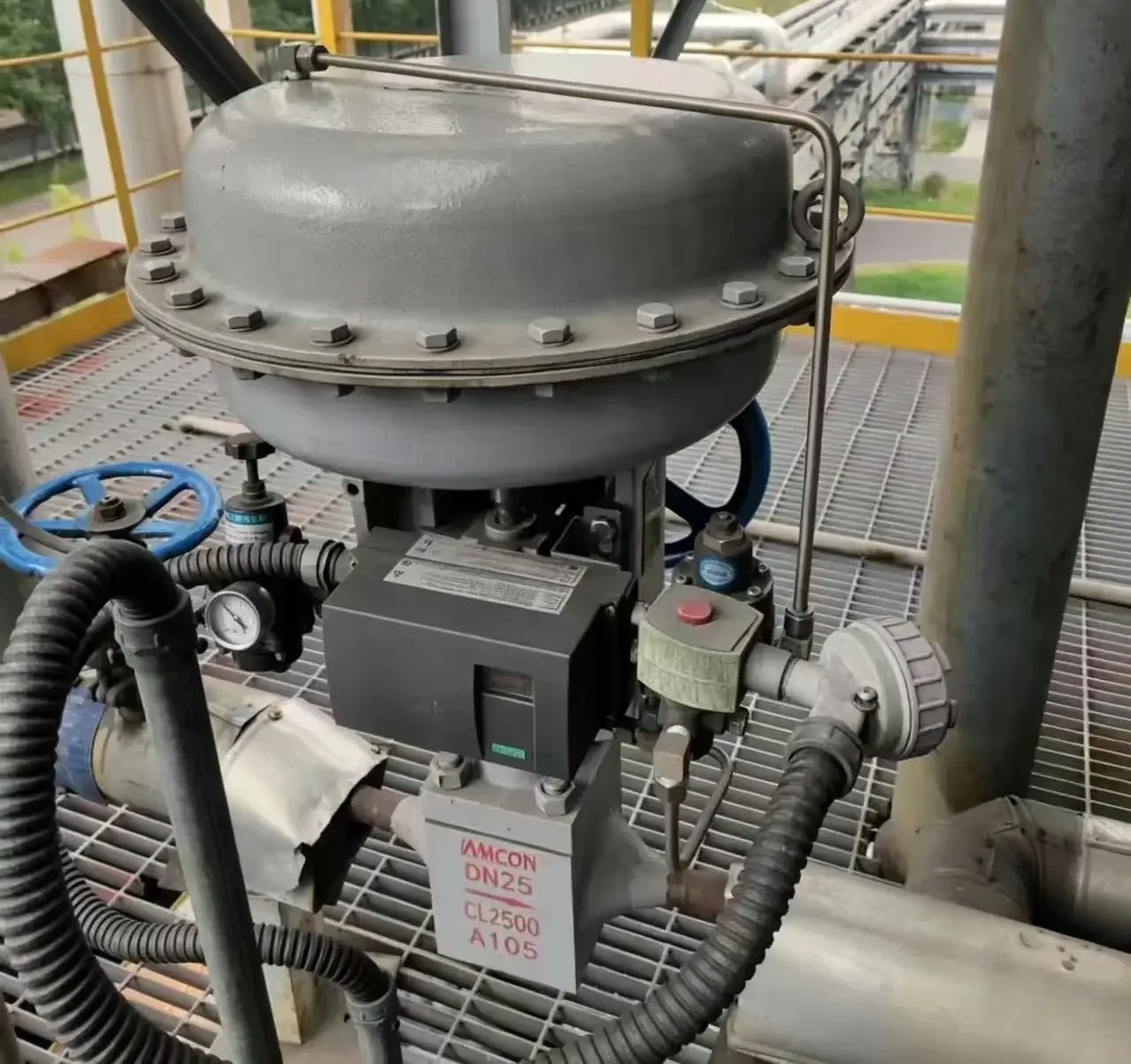
Common Symptoms of an Oversized Control Valve
Oversizing becomes a stronger possibility when several symptoms occur together: the valve operates near closure, small movements produce excessive flow changes, and the loop repeatedly overshoots its setpoint. Check whether this pattern persists during normal production or appears mainly after throughput falls.
Repeated hunting around the setpoint
The controlled flow, pressure or temperature repeatedly moves above and below its target while the valve keeps making corrections. Excess valve capacity can contribute to this cycle when a small opening change delivers more flow correction than the process needs. The controller then reverses the movement, and the cycle continues.
Hunting alone does not identify oversizing. Poor tuning, friction and disturbances elsewhere in the process can create similar oscillations. Actual valve travel must be compared with the command and process response before assigning the cause.
Large flow changes from small valve movements
A valve that feels unusually sensitive is another warning sign. A small, smooth stem or shaft movement may cause a flow change large enough to overshoot the required correction. This is especially troublesome when the valve assembly cannot reliably make the smaller adjustments the process needs.
Distinguish that response from a valve that initially stays still and then jumps. The latter points toward friction or another positioning problem, although an oversized valve can amplify its effect on flow.
Normal operation stays close to the closed position
If the valve supplies normal production flow while barely open, its installed trim may have substantially more capacity than the duty requires. The observation matters most when it represents sustained operation, rather than startup, shutdown or a brief low-demand period.
Use verified position feedback or actual stem or shaft travel. Controller output is not always equivalent to valve opening. There is no universal opening percentage below which every control valve is oversized; the selected trim’s characteristic and usable control range determine the significance of the position.
Frequent cycling and recurring wear
Persistent corrective movement can increase wear in packing, linkages and other moving components. Throttling close to the seat can also expose sealing surfaces to damaging flow conditions, depending on pressure drop, fluid properties and trim construction.
Recurring leakage, noise or vibration warrants investigation, but none is specific to oversizing. Damage records are useful supporting evidence when they agree with the operating trends; they cannot establish excess capacity by themselves.
Why an Oversized Valve Causes Control Problems
A control valve regulates flow by changing the restriction through its trim. When the installed capacity is too large for the duty, the valve must move closer to its seat to provide enough restriction. The required operating range can then occupy a small part of the available travel, leaving less useful movement for fine adjustment.
Excess capacity makes positioning errors matter more
The effect of a valve movement depends on the slope of its installed flow characteristic: how much flow changes as the valve moves in the actual piping system. A steep slope means a small position error produces a large flow error. This relationship, described as installed gain in the Valmet Flow Control Manual, connects valve positioning performance to process control.
At the same required Cv, linear and equal percentage trims can run at different travel positions. The same-duty characteristic comparison shows the distinction. A higher displayed position after changing characteristic does not by itself prove that capacity and installed gain now suit the process.
Every valve assembly has limits to how small and repeatable its movements can be. With excessive installed gain, those limits become more significant. Friction that causes the stem to stick and then release, or backlash that delays movement after a reversal, can create larger flow disturbances than the same positioning error would produce in a suitably sized assembly.
Changed operating conditions can make an existing valve oversized
A valve that once matched the process may become too large after production falls. Changes in pump operation, header pressure or downstream resistance can also alter the pressure drop available across it. For a given liquid flow within the applicable nonchoked flow conditions, a higher valve differential requires a smaller flow coefficient, moving the operating point toward closure.
This is why the original maximum-flow calculation cannot settle whether the valve suits its present duty. The installed trim and current pressure conditions determine where it operates. Nominal body diameter alone does not establish capacity, and different trims in the same body may provide substantially different operating ranges.
Controller tuning can improve the loop’s response, but it cannot change the physical capacity of the trim or eliminate mechanical positioning limits. If acceptable control requires movements the assembly cannot reliably produce, the capacity and installed characteristic need review alongside any tuning changes.
How to Confirm That the Installed Valve Is Oversized
A credible diagnosis connects the observed control problem to excess capacity in the installed trim. Start with operating records, then check whether the valve’s actual configuration explains its response under those conditions.
Compare the command, actual travel and process response
Place the valve command, position feedback, flow, controlled process variable and relevant pressures on the same time scale. Confirm that the feedback represents physical stem or shaft movement and that the flow measurement can resolve changes at the operating point. Split-range logic, signal characterization and incorrect feedback scaling can make controller output misleading. A controller output of 20% may therefore differ from 20% physical travel. An open or closed limit switch gives a discrete state, not a continuous position trend; the positioner and limit-switch guide explains which feedback can support this comparison.
| Observed behavior | Next check | Diagnostic implication |
|---|---|---|
| Travel follows smoothly, but small movements cause large flow changes | Installed trim curve and matching pressure conditions | Supports investigating excess capacity or unsuitable installed gain |
| Command changes while travel holds, then jumps | Friction, linkage, actuator pressure and positioner response | Investigate the motion chain before attributing the disturbance to sizing |
| Movement slows or stalls as demand or process load changes | Supply under demand and available actuator force or torque | Supply restrictions or insufficient actuator output may be involved |
| Actual travel oscillates despite a steady position demand | Positioner tuning, feedback linkage and pneumatic accessories | Investigate local positioning stability |
| Flow changes while actual travel remains steady | Synchronized valve differential, pump or header behavior and bypass condition | Investigate hydraulic or process disturbance; this pattern alone does not identify excess trim capacity |
If the command itself oscillates and travel follows faithfully, review controller tuning, measurement behavior and interacting process disturbances. Excess installed gain can still contribute, so faithful tracking does not rule out oversizing. Likewise, finding friction does not rule out a simultaneous capacity mismatch. Any deliberate movement test should follow the authorized site procedure.
Identify the trim actually installed
Use the valve tag and serial number to locate the original datasheet, sizing calculation and trim records. Check the rated flow coefficient, flow characteristic, seat or port size and rated travel against maintenance records. A replacement plug, seat or cage may have changed the capacity since commissioning.
The nameplate’s nominal size and pressure class cannot establish the current flow characteristic. If the installed trim cannot be identified, keep the capacity diagnosis provisional until configuration records or a planned inspection resolve it.
Test the capacity against current operating conditions
Reconstruct minimum, normal and maximum operating cases using each flow rate with its corresponding inlet pressure, outlet pressure, temperature and fluid properties. Account for losses between pressure measurement points and the valve. Keep occasional startup or peak duties separate from the conditions where the valve spends most of its operating time.
Calculate the required coefficient using the appropriate liquid, gas or steam method, then locate each requirement on the installed trim’s capacity-versus-travel curve. The control valve sizing guide explains the calculation branches and their limits.
Where measured travel is steady while flow varies, check the simultaneous pressure differential before interpreting the variation as valve gain. For the same liquid properties within a nonchoked turbulent regime, a pressure change can change flow without valve movement. Gas, steam, choking and changing phase require their own model. Compare predicted travel with the measured position. A substantial disagreement calls for checking the pressure basis, trim identity, feedback calibration and possible bypass flow before selecting a replacement. Oversizing is supported when the verified configuration meets frequent operating duties near its lower usable control limit and the observed flow sensitivity agrees with the installed-performance assessment. That finding provides a basis for evaluating lower-capacity trim or a different valve.
How to Fix an Oversized Control Valve
Once excess capacity is confirmed, compare the existing valve with configurations that provide useful adjustment across the current operating range. The correction must improve control at frequent low and normal loads while preserving the capacity needed for credible peak duties.
Use reduced-capacity trim when the existing body remains suitable
Some control valves accept a matched plug, seat or cage assembly with a lower rated flow coefficient. This can retain the existing body and piping connections while moving the required operating points farther from closure. It is a practical option when the body remains serviceable and the manufacturer offers compatible trim for the revised duty.
Check the proposed trim’s actual capacity curve and lower control limit. Changing from linear to equal-percentage trim may change the operating positions, but the characteristic name alone does not establish suitability. The low-flow selection checks remain necessary: smaller passages also need review for solids or deposits, and the new configuration must still satisfy pressure-drop, noise, shutoff and actuator-load requirements. For the severe-service construction comparison, see the cavitation and noise trim guide.
A maximum-travel stop does not provide the same correction. It limits how far the existing trim can open without changing its flow area at small physical openings. Signal remapping can alter the command-to-travel relationship, but it does not remove friction or improve the assembly’s mechanical resolution.
Replace the valve when compatible trim cannot meet the duty
Full replacement becomes appropriate when no compatible reduced-capacity trim is available, the available trims still cannot control the required low-flow duty, or the existing body and construction are unsuitable for continued service. Significant damage may also make retaining the assembly impractical.
Select the replacement from its installed performance, not simply by choosing the next smaller nominal size. Compare expected travel and flow sensitivity at the same operating cases used to assess the old valve. Recheck choking, cavitation or flashing where applicable, along with noise, velocity and actuator demand. A lower rated capacity is useful only if the complete assembly remains suitable for the service.
Verify the replacement interfaces before ordering
Compare the proposed assembly drawing with the existing installation. Matching nominal diameter and pressure class does not establish interchangeability. The review should cover:
- Piping connections: face-to-face length, flange standard, drilling and facing, or the exact weld or threaded connection details.
- Installation space: flow direction, actuator orientation, overall envelope, maintenance clearance, assembly weight and support requirements.
- Control connections: instrument-air or electrical supply, command signal, communication protocol, position feedback and accessory interfaces.
- Operating and failure action: required response to each named loss of air, power or command, shutoff differential and the actuator’s ability to move and seat the selected trim.
If a smaller body requires reducers, include their effect in the hydraulic review and confirm that the revised piping fits the available space. Reusing the old actuator also requires verification of mounting, stroke or rotation, available force or torque, and failure action with the new valve.
For a repair or change-out proposal, the MRO control valve replacement review connects nameplate identification with installation fit, current operating duty and control-interface checks. Keep confirmed matches, proposed differences and unresolved items visible before ordering.
Verify control after the change
After installation and calibration, evaluate the assembly under an approved commissioning procedure. Check repeatable response around low and normal operating points, required peak capacity, and the specified shutoff and failure functions. Revisit controller tuning because the relationship between valve movement and process response has changed.
Judge the result by stable, repeatable process control across the required duties. A higher displayed opening by itself does not demonstrate that the original problem has been resolved.
Choose the Right Correction for the Installed Valve
Hunting, sensitive flow response and persistent operation near closure justify an oversizing review. The decision to change capacity should follow from verified valve movement, the installed trim and current operating conditions. Where excess capacity is confirmed, compatible reduced-capacity trim may allow the existing body to remain in service; replacement is appropriate when that option cannot meet the duty. Check installation interfaces before committing to either change, then verify the result under operating conditions. Successful correction means repeatable control at low and normal demand while retaining the capacity and functions the process still requires. Use the troubleshooting guide when the evidence points to a mechanical or positioning fault rather than excess capacity.