

Rotary control valve selection starts with the flow passage and the duty. A characterized opening can help match capacity to the flow range; a suitable segmented design can accommodate fibrous or viscous media; and a butterfly valve can provide capacity in large pipelines. Each candidate still needs its own capacity, pressure-drop and torque checks.
V-port and segmented ball are overlapping descriptions. V-port names the opening shape; segmented ball names the closure element. A segment can have a V-notch. Compare full-ball V-port, segmented ball and modulating butterfly constructions rather than treating every catalog label as a separate design.
This comparison starts after rotary motion has been chosen. For the earlier decision, see the linear versus rotary control valve comparison.
How do the three rotary constructions differ?
The opening profile determines how flow capacity changes with rotation. The closure element and seat arrangement determine where the fluid passes, where solids can collect, and how the sealing surfaces contact each other. Comparing these features gives a clearer selection basis than the valve name alone.
Characterized full-ball V-port designs

A full-ball V-port design uses a complete spherical ball with a shaped flow opening. As the ball rotates, the V-shaped opening progressively exposes flow area. Different port profiles change both the available capacity and the rate at which capacity increases with movement.
This makes the port profile useful when matching a valve to a particular flow range. A smaller opening can provide lower capacity at a given position, but it must still pass maximum demand. The actual Cv curve establishes that trade-off; a V-port label alone does not establish low-flow performance.
For media that settle, crystallize or contain solids, inspect the spaces around the ball and seats. A shaped opening does not eliminate the possibility of material collecting in the body cavity. Seat design, particle characteristics and cleaning requirements can therefore change whether this construction is suitable. The V-port ball valve selection guide covers port-profile and seat choices in more detail.
Segmented ball designs, including V-notch trims
A segmented ball valve uses part of a spherical surface as its closure element. Its edge may have a V-notch or another characterized profile. The segment shape and shaft arrangement can leave a relatively open flow path, making this construction worth reviewing for viscous liquids and suitable streams containing fibers or suspended solids.
Where the segment edge passes against the seat, the closing movement can shear compatible fibers. That action does not mean the valve can cut hard particles or resist every abrasive slurry. Particle hardness, concentration and velocity still affect wear, while the seat, bearings and downstream surfaces need protection appropriate to the service.
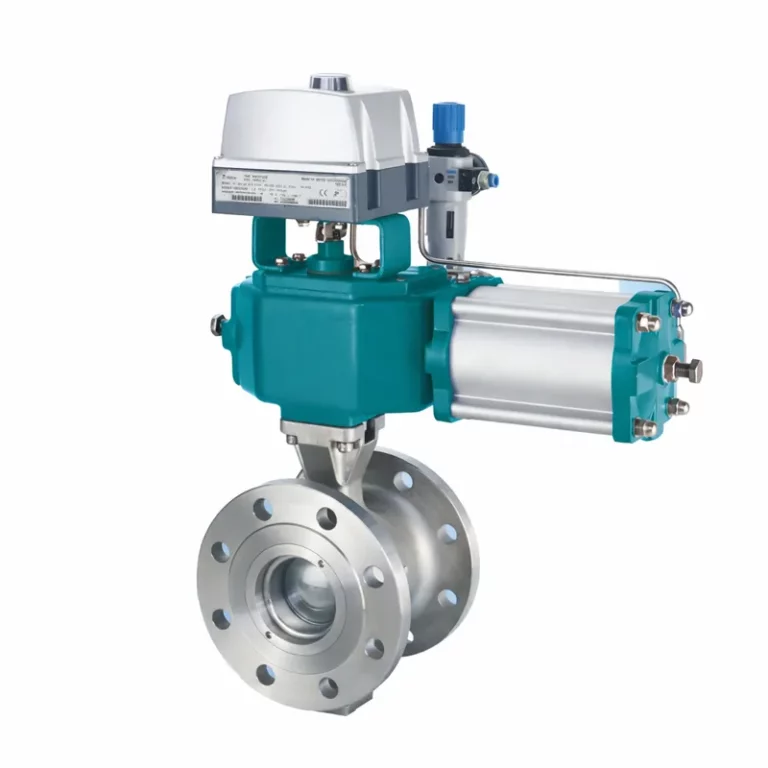
MacoTango’s V-port control ball valve uses a segmented ball with a V-shaped opening. It belongs to both descriptions, so it should not be counted as two separate construction options.
Butterfly designs for modulating service
A butterfly valve regulates flow by rotating a disc within the bore. Its compact body and high flow capacity make it a candidate for large pipelines, but the disc remains in the flow path. Disc position affects capacity, pressure recovery and the torque produced by the moving fluid.
The seat arrangement also matters. In a double-offset design, the disc moves away from seat contact early in opening, reducing rubbing through much of its travel. Triple-offset geometry further changes how the sealing surfaces separate and engage. These features address seating and wear; the number of offsets does not establish how well the valve controls low flow.
For continuous modulation, evaluate the specific disc’s Cv curve, permitted throttling conditions and torque demand. An isolation butterfly valve with an actuator fitted is not automatically a suitable control-valve assembly.
Which construction fits the medium and flow range?
Shortlist by medium and flow range, then check pressure drop at each operating point. A low-flow case with high pressure drop can be more demanding than maximum flow.
These are starting points for evaluation, not family-wide performance guarantees. Assess pressure drop against the actual fluid conditions and selected valve limits; no single pressure boundary applies to an entire construction family.
| Duty | Full-ball V-port | Segmented ball | Modulating butterfly |
|---|---|---|---|
| Clean liquid; wide flow range | Match port profile to both flow extremes. | Match segment profile and capacity. | Verify minimum-flow control and usable disc range. |
| Fibrous or viscous liquid | Check cavity buildup, seat contact and passage. | Consider where passage and cutting edge suit the fibers. | Check buildup at disc and shaft; verify seat compatibility. |
| Abrasive solids; substantial pressure drop | Review erosion at port, seats and cavity. | Review trim, bearing protection and downstream wear. | Use suitable disc, seat and lining; ordinary construction may not suit. |
| Large flow; little available pressure drop | Check capacity of the characterized port. | Check capacity and installed dimensions. | Consider capacity at usable positions and fluid torque. |
| Gas or steam; substantial reduction | Check choking, noise, outlet velocity and seat temperature. | Check compressible flow and required noise-control trim. | Check throttling limits, noise and dynamic loads. |
| Very low minimum relative to peak flow | Consider lower-capacity port profiles; retain peak capacity. | Review characterized or reduced-capacity options where available. | Verify the minimum lies in the validated control range. |
Some duties fall into several rows. A fiber-bearing slurry may favor a segmented V-notch construction for its passage and shearing action, while abrasive particles and high pressure drop require a separate wear assessment. Passing the fiber-handling check does not establish erosion resistance.
A butterfly valve can meet a large water line’s peak demand yet operate too close to its seat at low flow. Locate all operating cases on the selected curve; revise the size, trim or shortlist if one falls outside the permitted range.
Does the Cv curve cover minimum and maximum flow?
A rated Cv describes capacity at a stated valve position, usually the rated opening. To compare rotary control valves, use the complete Cv-versus-rotation curve. Two candidates with similar rated capacity can deliver very different capacities near the closed position, placing the same minimum-flow duty at different operating angles.
Locate each operating case on the capacity curve
Calculate the required Cv separately for minimum, normal and maximum flow, keeping each flow paired with its corresponding inlet pressure, outlet pressure, temperature and fluid properties. Then locate those required capacities on the candidate’s curve. Apply the relevant piping, viscosity and compressible-flow corrections as part of the sizing calculation.
The resulting positions show how much useful movement remains across the duty. If minimum flow falls below the manufacturer’s validated control range, adequate maximum capacity does not rescue the selection. If maximum flow requires more capacity than the permitted operating range provides, the candidate is too restrictive for that case.
For a full-ball V-port valve, changing the port profile can shift both low-opening capacity and maximum Cv. A segmented ball may offer different characterized or reduced-capacity options. For a butterfly valve, evaluate capacity at the permitted modulating positions rather than assuming its fully open Cv is available for normal control. Each construction needs its own curve; equal shaft angles do not imply equal flow capacity.
Separate port angle, shaft rotation and installed flow
A V-port’s notch angle describes the opening geometry. Shaft rotation describes the valve’s operating position. These are different quantities: selecting a narrower notch changes the capacity curve, while rotating the shaft moves the valve along that curve. Check which quantity a drawing or chart labels before comparing data.
The inherent flow characteristic describes capacity change with travel under constant pressure drop. In the installed system, pressure drop usually changes with flow as the pump, piping and downstream equipment interact. The resulting flow-versus-position relationship can therefore differ substantially from the catalogue characteristic.
Catalogue rangeability also needs context. It describes a capacity range under defined conditions; it does not guarantee the same maximum-to-minimum flow ratio in the plant. At the low end, friction, backlash and positioning resolution can limit useful control even when the capacity curve includes the required Cv.
Cv data needed for a meaningful comparison
Use the following information to evaluate each proposed configuration:
- Configuration identity: valve size, port or segment profile, disc design, seat arrangement and flow direction.
- Capacity curve: Cv or Kv at stated rotation angles, including the rated opening and a clear coefficient basis.
- Validated control range: the usable travel limits and the conditions supporting any rangeability claim.
- Sizing coefficients: applicable pressure-recovery and choking factors matched to the selected trim and position.
- Operating-case results: predicted position and relevant flow-limit checks for minimum, normal and maximum duty.
A proposal containing only nominal diameter and maximum Cv leaves the low-flow decision unresolved. Prefer the candidate whose documented operating range covers the actual duty, with usable movement around normal flow and sufficient capacity at peak demand.
Can the valve withstand the actual pressure-drop conditions?
Two rotary valves with the same pressure class can have different limits in throttling service. Their flow passages produce different local pressures and velocities, while their seats and actuators impose separate operating limits. A candidate must pass both the flowing conditions and the required shutoff condition.
Operating pressure drop, shutoff differential and body rating
Operating pressure drop is the difference between inlet and outlet pressure while the valve controls flow. Evaluate it at minimum, normal and maximum flow using the pressures that occur together. Low flow can coincide with a large pressure drop, concentrating the pressure reduction across a small opening.
Shutoff differential is the pressure difference the closed valve must withstand while meeting its specified leakage requirement. It can exceed the normal operating differential, particularly when downstream pressure falls or upstream pressure rises after closure. The seat, shaft and actuator must suit that condition, including the required pressure direction.
Body pressure-temperature rating defines the pressure boundary for the selected construction and material at temperature. It does not establish an acceptable continuous throttling differential. A body may contain the pressure while the trim suffers cavitation damage or the actuator cannot deliver the required closing torque.
Liquid service: cavitation and flashing
In liquid service, pressure falls as fluid accelerates through the restriction, then partly recovers downstream. If the local pressure falls below the liquid’s vapor pressure, vapor bubbles can form. When pressure subsequently recovers enough to collapse those bubbles, cavitation occurs. If downstream pressure remains below vapor pressure, vapor persists and the service involves flashing.
The opening geometry affects that pressure recovery. Use the liquid pressure recovery factor, FL, for the actual valve, trim and operating position when assessing liquid choking. A cavitation assessment also needs the applicable manufacturer method and operating limits; FL alone does not establish a damage-free operating range.
A V-shaped opening does not by itself prevent cavitation. Neither does the open passage of a segmented ball or the reduced seat rubbing of an offset butterfly valve. Erosion-resistant surfaces may tolerate damage better, but they do not remove the pressure conditions that create vapor. Where necessary, evaluate a rotary design with purpose-designed pressure-reduction trim or revise how pressure is distributed through the system.
Gas and steam: choking, noise and outlet velocity
For gas and steam, check compressible-flow behavior using absolute inlet pressure, temperature and the valve-specific pressure differential ratio factor, xT, with the applicable sizing corrections. Choked flow limits how much additional flow a further reduction in outlet pressure can produce. Noise and outlet velocity still require evaluation, even when the calculated Cv appears sufficient.
Special trim can change both capacity and pressure-recovery behavior. Any change to the port, segment, disc or flow direction therefore needs matching sizing data. The control valve sizing guide explains the liquid, gas and steam calculation paths in more detail.
Can the actuator move and seat the valve throughout travel?
An actuator must provide enough torque wherever the rotary valve needs it, in both directions of movement. Its highest catalogue output may occur at a different shaft angle from the valve’s highest demand. Compare the valve’s required torque with the actuator’s available output throughout travel, including the required failure movement.
Breakaway, running and seating torque
Separate the torque demands through the stroke:
- Breakaway: starts movement from closure; seat contact, pressure loading and friction matter. Long stationary periods or deposits can increase demand.
- Running: keeps the valve moving through intermediate positions.
- Seating: completes closure and establishes the required seat contact.
Identify each demand even when one governs actuator selection.
In full-ball V-port and segmented ball valves, pressure acting on the ball or segment combines with seat, packing and bearing friction. The contact arrangement matters: a segment that remains against its seat has a different friction pattern from an eccentric closure element that moves away from the seat during opening. The word “segmented” alone does not establish which arrangement is present.
For butterfly valves, fluid forces on the disc create torque that changes with opening, pressure drop and flow direction. Reduced seat rubbing in an offset design does not remove this load. An actuator selected only from the torque needed to unseat the disc may therefore be inadequate at an intermediate position.
The valve torque data must identify its basis, including seat construction, temperature, pressure conditions, flow direction and any allowance for service-related friction. Keep those allowances visible so they are neither omitted nor added twice.
Define the required failure movement
Define the failure response for each relevant loss of supply or signal. “Fail-safe” alone does not tell the supplier whether the valve must close, open or remain in position, or which pressure load applies during that movement.
Pneumatic supply and spring-return curves
For a pneumatic actuator, use the minimum air pressure available at the actuator during movement. Header pressure alone may overstate the usable supply if the regulator, tubing or accessories restrict flow. A double-acting actuator needs adequate output in both directions under that supply condition.
A spring-return actuator has separate air-stroke and spring-stroke torque curves. Both must exceed the corresponding valve demand throughout the required movement, with the specified design allowance. For fail-close duty, the spring must complete closure against the applicable pressure and seating load. For fail-open duty, it must reach the required open position against the opposing loads. Check the complete curves as well as their endpoints.
Electric actuation and the mechanical torque limit
Electric actuators also need configuration-specific checks. Available output, torque-switch settings, permitted modulating duty and any stored-energy failure function must match the valve duty. A command to move on signal loss does not establish that the actuator can move after electrical power is lost.
Higher actuator output is limited by the valve shaft, coupling and mounting assembly. Check the maximum torque the actuator can transmit, including at maximum supply or its configured torque limit, against those components’ allowable loads.
Compare the valve-demand and actuator-output curves on the same supply, pressure, temperature, direction and fail-action basis. Then check positioning behavior: adequate torque does not prove small, repeatable movements during modulation.
Select the complete configuration, not the valve label
Carry forward the configuration whose passage suits the medium, whose Cv curve covers the actual flow range and whose actuator meets the full torque demand. A V-notch label or a high rated capacity cannot establish those results. The selected trim, seat and actuator must meet the same operating and shutoff cases.