

Flashing and cavitation both begin when liquid vaporizes as pressure falls through a control valve. The difference is what happens after the restriction: cavitation involves bubble collapse as pressure recovers; flashing leaves vapor in the downstream flow. That difference determines whether the remedy should control collapse or accommodate a sustained two-phase stream.
Pitting, washed surfaces, and noise help direct an investigation, but they do not establish the cause on their own. Particle erosion and corrosion can occur alongside either mechanism. Compare the pressure conditions with the location and character of the damage before choosing replacement trim.
Follow the pressure recovery to distinguish flashing from cavitation
Liquid accelerates through the restriction and reaches its smallest effective flow area near the vena contracta. This point is typically downstream of the physical opening. Static pressure is low there, then partly recovers as the stream slows. The recovered outlet pressure can therefore be higher than the minimum pressure inside the valve.
- P1: inlet pressure for the operating case.
- Pvc: local minimum pressure near the vena contracta.
- Pv: vapor pressure for the liquid composition and relevant temperature.
- P2: recovered outlet pressure.
Use absolute pressure when comparing a process pressure with vapor pressure. For a simple liquid screening model, Pvc below Pv allows vapor to form; recovery above Pv allows collapse. P1 and P2 alone do not reveal Pvc. Valve geometry, recovery characteristics, and operating position affect the internal pressure path. Record where the pressure taps are located. A downstream vessel reading may include piping losses, elevation effects or another restriction between the valve and vessel; it is not automatically the recovered pressure at the valve outlet. Use a consistent valve-and-piping model when assessing the pressure path.
| Mechanism | What happens in the flow | Design question |
|---|---|---|
| Cavitation | Vapor forms locally, then collapses as pressure recovers. | Can local vapor formation or damaging collapse be reduced? |
| Flashing | Vapor remains in the downstream stream. | Can the outlet and piping handle the two-phase flow? |
| Particle or jet erosion | Impact and shear remove material; bubble collapse is not required. | Where does the stream strike, and what drives the wear? |
For hot liquids or mixtures with substantial flashing, outlet phase fraction and temperature require an appropriate thermodynamic calculation. A single vapor-pressure comparison does not quantify the amount of vapor or the outlet velocity.
A choking result answers a different question
Choked flow means that, at fixed opening and unchanged upstream conditions, reducing downstream pressure further no longer increases flow. It is a capacity limit, not a measure of damage rate. Cavitation can begin before full choking, and a choked valve does not necessarily suffer destructive cavitation. The control valve choked-flow guide explains the sizing consequence.
Use damage patterns to decide what evidence to check
The location and texture of metal loss help identify which pressure and wear mechanisms to investigate. Link those observations to the operating case in which noise, vibration, or loss of performance occurred. Different loads can expose the same valve to different pressure conditions, so one normal-duty reading may miss the damaging condition. Pair flow, inlet pressure, outlet pressure, temperature and actual travel from the same operating period. Include the loads or transients associated with the damage, rather than combining unrelated maximum and minimum readings into an invented duty. Assess each real case separately: the greatest pressure drop and the lowest outlet pressure may occur at different loads.
If the service is confirmed as single-phase gas or vapor, noise is not evidence of liquid cavitation. Investigate aerodynamic or mechanical sources instead; the gas and steam noise section explains the flow-noise distinction. If liquid is entrained or a phase change occurs, establish the actual fluid state before applying a single-phase explanation.
Pitting and crackling: investigate bubble collapse
Rough pits or a honeycomb-like surface, especially near a recovery or jet-impact region, support a cavitation hypothesis. Check whether the liquid state and the selected trim’s recovery behavior allow local vapor formation followed by collapse. Crackling or vibration adds context but cannot exclude particle impact or mechanical looseness.
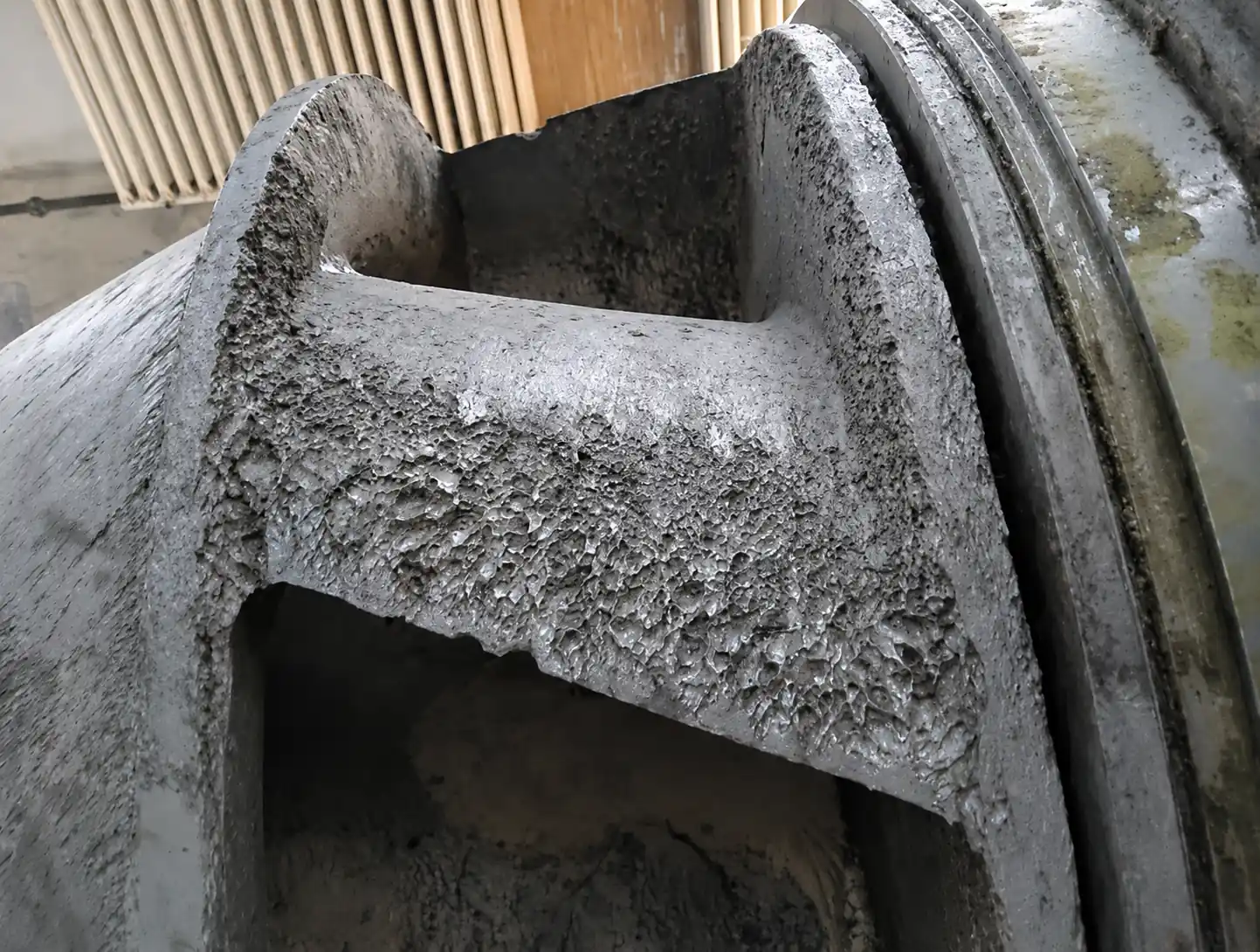 Surface morphology helps locate the investigation; this photograph alone does not establish the operating cause.
Washed surfaces and outlet wear: investigate persistent two-phase flow
Smoothly worn areas or directional metal loss at the outlet can point toward an erosive two-phase jet. Compare the outlet state with the liquid’s phase behavior and inspect where the stream changes direction. Flashing can damage the body and downstream pipe even when the trim is the component first removed for inspection.
Grooves, edge loss, or deposits: consider additional mechanisms
Solids can cut or strike the flow passage without cavitation. Corrosion can weaken a surface that the stream then removes. Document particle loading, corrosion products, coating separation, and the direction of wear instead of forcing every damaged surface into a single category.
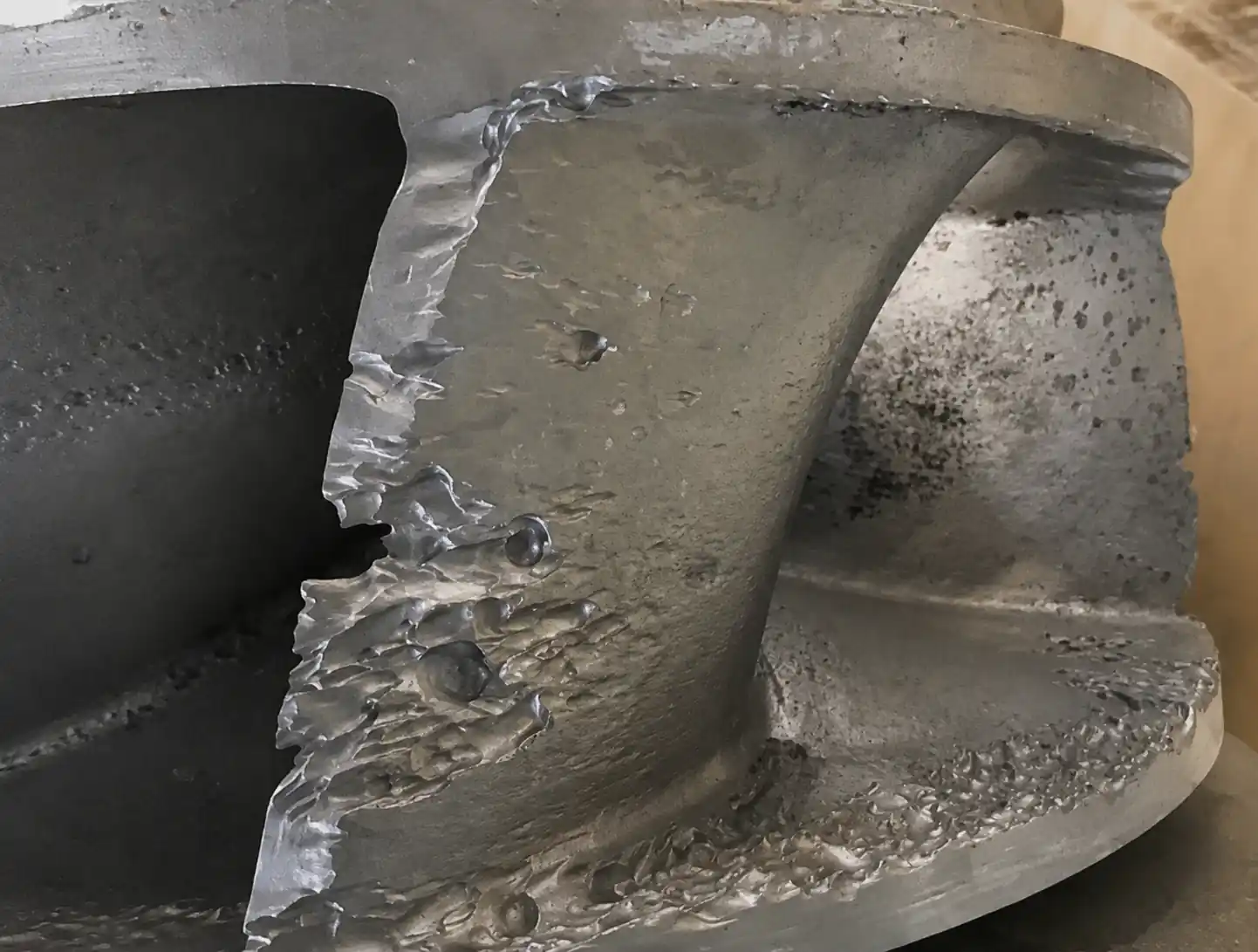 Edge loss and pitting can coexist. Interpret their location together with process and inspection records.
Check the flow path beyond the seat
- Trim outlet and body: locate where the jet or collapse region meets the metal.
- Reducers and transitions: look for concentrated wear around area changes.
- First downstream elbow: examine the region exposed to the turning stream.
- Downstream pipe: compare wall-thickness readings at known wear locations over time.
Internal inspection requires the site’s isolation, depressurization, and access procedures. Preserve photographs and location records before cleaning. Review measured flow, pressure, temperature, and travel for the affected operating cases; a low opening by itself is not a cavitation diagnosis. The control valve sizing guide connects those cases to capacity and operating travel.
Choose cavitation mitigation around the internal pressure path
Two approaches address different parts of the mechanism: keep the local pressure from falling into the vapor-forming region, or arrange the flow so that unavoidable collapse causes less damage. The appropriate choice depends on severity, flow range, cleanliness, and the pressure conditions that the process must maintain.
Staged pressure reduction for a suitable liquid duty
A multistage trim distributes the pressure reduction through successive restrictions. Its value comes from controlling the local pressure and velocity within those stages. A stage count alone does not prove protection: the pressure allocation, available capacity, operating position, and final outlet state still matter.
Small passages can plug when solids or deposits are present. Check whether the selected construction can pass the actual contaminants while maintaining the intended pressure distribution. Multi-hole trim can divide a jet without necessarily providing the same pressure path as a true multistage arrangement; use the specific design data.
Manage where the jets and collapse regions meet
Some anti-cavitation constructions direct jets and bubble collapse away from vulnerable surfaces. This can reduce damage where eliminating all vapor formation is impractical. It does not make the material immune to wear or remove the need to assess the full flow range.
Treat an added restriction as a system change
A downstream restriction can redistribute pressure drop, but its effect changes with flow. A fixed restriction that creates useful backpressure at high flow may provide much less at low flow. Recheck both devices and the connecting pipe; otherwise the change can move damage downstream or leave the low-flow duty unprotected. Valmet’s liquid-flow manual explains this behavior for baffle and orifice arrangements.
Raising downstream pressure is not a universal cure. If vapor still forms inside the valve and then collapses in a vulnerable region, a changed pressure profile can create a different damage problem. Any process-pressure change needs assessment against the required operating duty.
For flashing, design for the vapor that remains
When the required outlet state is two-phase, staging inside the valve cannot make the final stream entirely liquid. Focus on the discharge path and the exposure of the valve body and downstream piping.
An appropriate angle-body or enlarged-outlet arrangement may reduce abrupt turning or provide more discharge area. The actual choice depends on the calculated two-phase state, velocity, and impingement locations. A larger outlet connection alone is not proof that the downstream piping is protected.
Review transitions and elbows together with the valve, especially where the mixture accelerates or strikes a wall. Particle loading and corrosion add separate wear mechanisms. If process conditions can be changed, assess whether that changes the outlet state; otherwise select a flow path and materials that accommodate the flashing duty.
Use material protection for the exposure that remains
Hardfacing, coatings, and wear-resistant trim can improve resistance in a suitable application, but none corrects an unsuitable pressure path. Select the base material and any surface treatment together, considering corrosion, temperature, impact, and the geometry of the exposed part.
A hardness number does not describe the whole protection system. Layer thickness, bond quality, toughness, finishing, and substrate condition affect whether a surface survives the duty. A thin coating used for sliding wear may not suit repeated impact; a harder material may also be more brittle. Compare material data on the same test and service basis rather than ranking unlike hardness values.
Repair the damage or change the design?
A like-for-like trim repair can be reasonable when inspection confirms that the retained assembly is fit for service and the original design still suits the duty. If pitting returns under the same pressure conditions, review the pressure-reduction design before ordering the same parts again. For persistent flashing, assess the outlet and downstream wear path; replacing the seat does not correct an unsuitable discharge path.
Damage to the body or downstream pipe needs a separate assessment of fitness for service. A trim replacement does not establish pressure-boundary integrity. The repair, replacement and reselection checks explain how to compare the routes once the mechanism and inspection scope are clear.
A replacement trim can restore capacity while the original damaging pressure conditions remain. Compare subsequent noise, travel, and wall-thickness trends at comparable operating points. During the next planned inspection, compare the same locations for renewed pitting, directional wear, coating loss, or plugged passages.
If damage returns in the same region, revisit the pressure and jet path as well as the material. The trim guide for cavitation and noise provides a separate comparison of construction options once the service mechanism is established.
Match the remedy to collapse, persistent vapor, or particle wear
Choose cavitation measures from the pressure recovery and collapse conditions. Choose flashing measures from the two-phase outlet state and discharge path. Where solids or corrosion contribute, address those exposures as well. The useful test of a remedy is whether it changes the mechanism at the damaged location across the relevant operating cases, not whether the replacement trim is simply harder.