

A correctly sized water treatment control valve can still fail early if its trim, materials, pressure drop, or actuator speed do not suit the service. Clean water, chemical dosing, backwash, sludge, and reuse lines impose different demands. Low-flow control, corrosion, suspended solids, cavitation, and pump-related pressure changes each affect valve selection.
This guide explains how to select control valves for water treatment and wastewater systems. It also covers desalination duties where high pressure, reverse osmosis, brine, or chloride exposure changes the design.
Start with each valve’s P&ID duty: feed regulation, dosing, and backwash switching need separate assessment. For product matching and quotation support, see MacoTango’s water treatment control valve solutions.
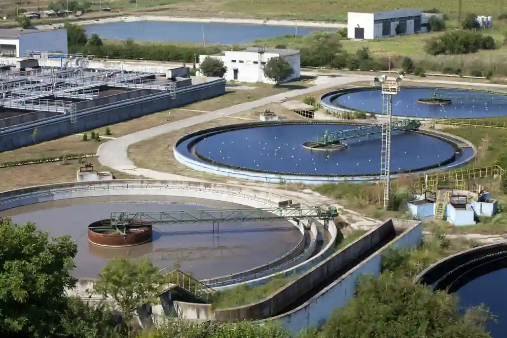
Where Control Valves Are Used in Water Treatment Systems
Different treatment stages ask the control valve to solve different problems. A valve on a raw water line may mainly stabilise flow from a pump, while a dosing valve may need fine control at a much smaller flow rate and better chemical compatibility.

Raw Water Intake and Pumping Lines
Raw water intake lines and pump discharge lines often need flow or pressure regulation before the water enters the main treatment process. The valve may see changing pump pressure, suspended sand, or unstable flow when pumps start and stop. In these positions, the actuator response and valve characteristic matter because fast movement can make pressure fluctuation worse instead of correcting it.
Filtration and Backwash Control
Filtration systems use control valves to manage flow through filter beds, membranes, or backwash lines. The valve duty can shift between steady regulation and frequent movement during cleaning cycles. If the valve is selected only by pipe size, the trim may not handle repeated throttling, changing differential pressure, or particles released during backwash.
Chemical Dosing Lines
Chemical dosing valves usually handle smaller flow rates than main water lines, but the material risk is higher. Chlorine, coagulants, acids, alkalis, and other treatment chemicals can change the body, trim, seat, diaphragm, and packing choice. A valve that works in clean water may be unsuitable on a dosing line if the wetted parts are not checked against the chemical concentration and temperature.
Wastewater and Sludge Handling
Wastewater valves may need to pass fibres, biological solids, grit, or sludge without sticking or losing control. This is where the selection moves away from clean-water assumptions. The valve must be reviewed for clogging risk, erosion, seat wear, actuator force, and whether the flow path can tolerate suspended solids.
Desalination and Water Reuse
Desalination belongs inside the wider water treatment selection problem when reverse osmosis pressure, brine, or chloride corrosion changes the valve duty. These lines may need closer pressure control, better corrosion resistance, and more careful review of cavitation or flashing risk. The desalination duty should be treated as a high-pressure or corrosive water service, not as the whole article topic.
Service Conditions That Change the Valve Choice
Clean water, wastewater, and dosing service can share the same nominal pipe size but require different control valve construction. The selection changes when the fluid carries solids, attacks the wetted parts, creates a high pressure drop, or needs a defined fail position during pump or power loss.
Clean Water Still Has Sizing Risk
Clarified water is usually less abrasive than wastewater, but it can still create unstable control if the valve is oversized or works too close to the seat. Low-flow regulation may need reduced trim, a suitable flow characteristic, and enough actuator resolution to avoid hunting around the set point.
Wastewater Adds Solids and Clogging Risk
Wastewater valves may see fibres, grit, biological solids, or sludge that can collect around the seat and trim. A narrow flow path may give accurate control in clean water but become a maintenance problem in dirty water. The valve body style, trim geometry, seat design, and actuator force should be checked against the solids content before the valve is treated as a standard water duty.
Chemical Dosing Changes Wetted Materials
Chemical dosing lines put more pressure on material compatibility than on large flow capacity. Chlorine, coagulants, acids, alkalis, and cleaning chemicals can affect the body, liner, trim, seat, packing, and diaphragm materials. PTFE-lined or corrosion-resistant designs may be needed when a normal carbon steel or stainless steel valve cannot tolerate the concentration, temperature, or cleaning cycle.
Pressure Drop Changes Trim Selection
A pressure-reducing valve in a water line can create cavitation, flashing, vibration, or noise when the pressure drop is too high for standard trim. Pump discharge lines, distribution pressure control, membrane systems, and some reuse or desalination circuits need closer review because the valve may be controlling both flow and stored hydraulic energy.
Actuator Speed and Fail Action Affect Plant Safety
The actuator is part of the water treatment valve selection, not an accessory to decide at the end. Fast closing can increase water hammer risk, while weak actuator force near the seat can make shut-off or stable throttling harder. Fail-open, fail-closed, or fail-last action should match the plant logic, especially around chemical dosing, pump protection, bypass lines, and treated water distribution.
RO concentrate control is a separate valve duty
An RO concentrate valve restricts the reject path to help establish flow balance and recovery. Assess its flow range, pressure drop, and startup position separately from UF feed control, explained in the UF skid feed-flow guide.
- Flow and pressure: Use concentrate flow and pressures immediately upstream and downstream of the valve at the same operating state. Account for drain, header, or energy-recovery conditions. Total feed flow, pump pressure, and membrane pressure drop cannot substitute for these values.
- Control range: Check minimum, normal, and maximum concentrate flows, plus startup, shutdown, and flushing where the valve participates. Assess usable trim range, liquid pressure-recovery data, and outlet layout. Pressure class alone does not establish throttling suitability.
- Wetted materials: Check concentrate chemistry, temperature, chloride content, and cleaning media that reach the valve. Assess corrosion, deposits, and erosion across the body, trim, seat, and seals.
Use the cavitation and flashing distinction to assess vapor formation and downstream pressure recovery. Do not assume every RO reject valve cavitates.
Recovery is a system result, not a percentage valve opening. DuPont’s FilmTec startup sequence warns that starting against a closed or nearly closed concentrate valve can exceed design recovery and promote scaling.
Follow the membrane and skid supplier’s sequence for the actual configuration. This example does not define a universal opening setting, closing time, or fail position.
Within a water-treatment skid valve package, identify the concentrate valve as its own P&ID item, with its pump, membrane, energy-recovery, and control interfaces. Capacity, materials, and assembly acceptance remain specific to this duty.
Which Control Valve Types Fit Common Water Treatment Duties
Valve type selection starts from the control duty, then the medium and pressure drop narrow the options. A clean-water flow loop, a chemical dosing line, and a sludge-bearing wastewater line should not be pushed into the same control valve design just because the nominal pipe size is similar.
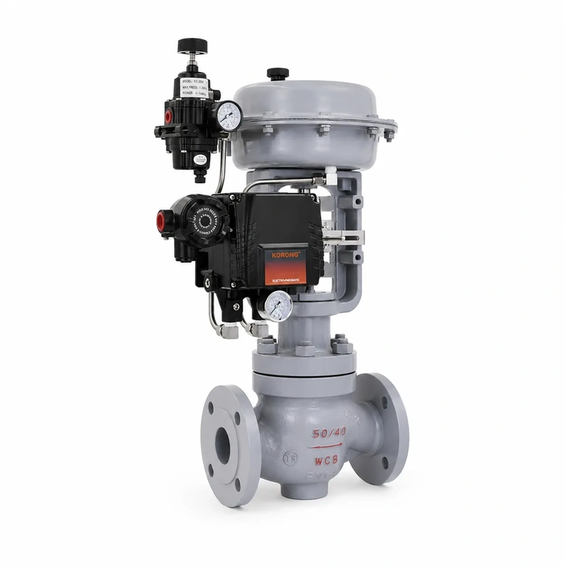
| Water Treatment Duty | Common Control Valve Choice | Selection Boundary |
|---|---|---|
| Clean water flow or pressure control | Single-seat or globe-style control valve | Check Cv, shut-off class, low-flow stability, and actuator resolution. |
| Pressure reducing or higher differential pressure service | Cage-guided, sleeve, or anti-cavitation trim design | Review cavitation, flashing, noise, trim velocity, and downstream pressure recovery. |
| Wastewater, sludge, or solids-bearing flow | Segmented ball or V-port rotary control valve where the flow path suits the solids | Check clogging risk, seat wear, solids size, erosive velocity, and actuator force. |
| Chemical dosing or corrosive water service | PTFE-lined, corrosion-resistant, or material-selected control valve | Match body, liner, trim, seat, packing, and diaphragm materials to the chemical. |
| Mixing, bypass, or diversion around treatment equipment | Three-way control valve where the process genuinely needs mixing or diverting | Confirm flow direction, pressure balance, port arrangement, and control range. |
The table should be used as a first screening step, not as a final specification. A valve type that fits the duty can still fail if the trim material, seat design, actuator sizing, or fail action is wrong for the actual water quality and pressure drop.
MacoTango lists the main industrial control valve series separately, so the product page can be checked after the application duty and service limits are clear.
Pressure Drop, Cavitation and Water Hammer in Water Lines
A pressure-reducing water valve can damage trim and downstream piping when the local pressure inside the valve falls too low or when the valve closes too quickly.
High Differential Pressure Can Create Cavitation
When water accelerates through the valve port or trim, pressure drops at the narrowest flow area. If that local pressure falls below the water vapour pressure and then recovers downstream, vapour bubbles can collapse inside or near the valve. The result is often noise, vibration, rough trim damage, and unstable control.

Standard trim may be acceptable for a moderate pressure drop, but pump discharge control, distribution pressure reduction, membrane feed pressure, and some reuse or desalination circuits can need a different trim design. Only a trim designed for staged reduction divides the pressure drop into successive stages. A multi-hole cage or sleeve name alone does not establish staging or anti-cavitation performance. Review the selected trim’s pressure-recovery data and predicted behavior for each operating case.
Flashing Needs Material and Geometry Review
Flashing is different from cavitation because the downstream pressure stays below the vapour pressure and the vapour does not collapse back into liquid inside the valve. In water service this can combine erosion and corrosion, especially when high velocity attacks a steel surface or seat area. The valve cannot always remove the system condition that causes flashing, so the geometry, outlet velocity, trim hardness, and body material need closer review.
Fast Valve Movement Can Increase Water Hammer Risk
Water hammer is caused by a sudden change in flow velocity. A control valve that closes too fast near a pump station, backwash line, or distribution header can create a pressure surge that travels through the pipeline. The risk is higher when the actuator movement, valve characteristic, pump trip logic, or downstream volume is not matched to the hydraulic system.
Assess the complete movement-versus-time profile and pump events before changing speed or fail action. Slower total closure is not a universal surge solution, and check-valve reversal is a separate dynamic problem. Use the water-hammer event and system checks to organize the transient review. The safest selection normally starts with the actual flow rate, inlet pressure, outlet pressure, temperature, fluid density, and expected operating range. When the duty is pressure-sensitive, a control valve Cv calculator can help check the first sizing step before trim and actuator details are reviewed.
Material, Trim and Sealing Choices for Water, Chemicals and Wastewater
Material selection in water treatment is often decided by the chemicals, suspended solids, and pressure drop, not by water alone. The valve body may meet the pressure rating while the trim, liner, seat, or packing becomes the weak point in actual service.
Body Material Depends on Corrosion and Project Standards
Carbon steel or cast steel may be acceptable for some clean-water and low-corrosion duties, but it should not be assumed for chemical dosing, chloride-containing water, or reuse lines. Stainless steel, duplex, alloy, or lined construction may be needed when the water contains chlorides, oxidising chemicals, acids, alkalis, or cleaning agents. Temperature and concentration matter because a material that works in diluted chemical service may not tolerate a stronger dosing point.
Trim Takes the Highest Velocity
The trim sees the highest velocity and the strongest pressure change inside the valve. In clean water, standard trim may be enough when the pressure drop is moderate. In wastewater, high differential pressure, or erosive service, the plug, cage, sleeve, ball segment, and seat area may need harder materials, a larger flow path, or a design that reduces direct particle impact.
Lined Valves Help in Dosing and Corrosive Water
PTFE-lined or fluorine-lined control valves can protect the metal body from corrosive media in chemical dosing and treatment lines. The lining does not remove the need to check pressure, temperature, vacuum risk, particle abrasion, and connection design. A lined valve can be the right answer for corrosive liquid, but it may be the wrong answer if abrasive solids or high velocity damage the liner.
Seats, Packing and Soft Parts Need Compatibility Checks
Seat and packing materials affect shut-off, external leakage, friction, and maintenance. PTFE, elastomers, graphite, or other sealing materials should be checked against the chemical, temperature, pressure, and required leakage class. In frequent throttling service, a soft seat may give tighter shut-off but can wear faster if the water carries grit or if cavitation occurs near the seat line.
The safest material decision is made after the medium is described clearly: clean water, treated water, wastewater, sludge, dosing chemical, brine, or reuse water. Each one changes the balance between corrosion resistance, erosion resistance, leakage performance, and actuator force.
Review the Water Treatment Duty Before Final Sizing
Final sizing should start from the actual water duty, not from the valve size in the pipeline schedule. Flow range, inlet pressure, outlet pressure, temperature, solids content, dosing chemical, required fail action, and allowable pressure fluctuation all affect the valve body, trim, material, actuator, and positioner choice.
If the line handles clean treated water, the main risk may be oversized trim or unstable low-flow control. If the line handles wastewater, sludge, or backwash flow, the main risk may move toward clogging, erosion, and seat wear. If the line handles chemical dosing, reuse water, brine, or high-pressure membrane service, material compatibility and cavitation review become part of the same selection decision.
MacoTango can review water treatment control valves against the actual medium, pressure drop, flow range, material requirement, and actuator fail action. For project-specific sizing or product matching, use the dedicated water treatment control valve solutions page or contact MacoTango with the working conditions that define the valve duty.