

A back pressure valve, or back-pressure regulator, controls pressure upstream by adjusting the flow leaving a vessel or process line. It opens further as upstream pressure rises and restricts outflow as pressure falls. Its purpose is normal pressure regulation. Reverse-flow prevention and protection against abnormal overpressure require separate assessment; neither function follows automatically from the name “back pressure valve.”
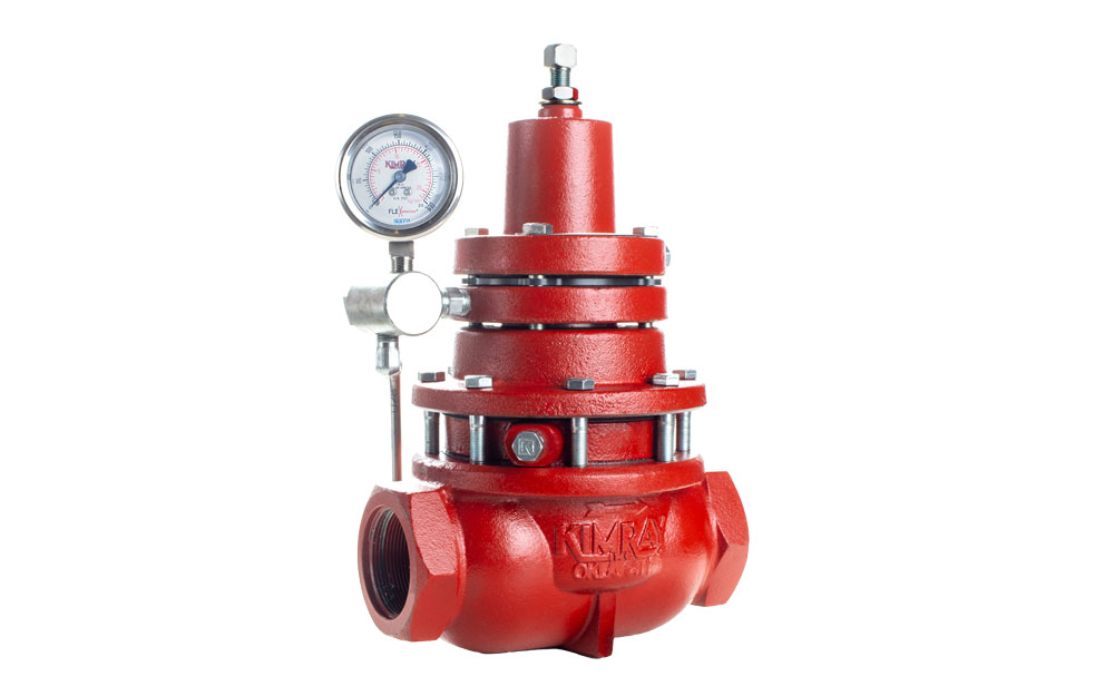
source:Kimray
How Does a Back Pressure Valve Work?

source:WRS Dosing Pump
Spring-loaded diaphragm designs use a balance between sensed upstream pressure and spring force. The components below describe that general arrangement; pilot-operated and other constructions can transmit the forces differently.
- Inlet and outlet: Fluid passes from the upstream process through the valve to a lower-pressure destination. The available pressure difference and flow capacity limit how much fluid the valve can pass.
- Adjustment nut and spring: Changing spring compression changes the loading force and regulated pressure setting. The actual pressure under flow must be checked against the regulator’s operating curve.
- Diaphragm: Sensed pressure produces a force on the diaphragm. In a direct-operated design, the changing force balance moves the throttling element. The pressure connection and wetted parts depend on the construction.
- Valve seat and shaft: The moving element changes the flow area at the seat. Its linkage and direction of physical movement are design-specific; the required control response is greater opening as upstream pressure rises.
- Seals: Body seals and the seat have different leakage duties. Confirm their materials and specified leakage performance; a regulating valve is not automatically a leak-tight isolation device.
- Protective Cover: The adjustment nut has a protective cover to keep the adjustment mechanism safe from dust and contaminants.
Working Principle:
- A rise in sensed upstream pressure changes the force balance on the diaphragm.
- The throttling element moves toward a larger opening, increasing the available flow area.
- More fluid can leave the upstream process if the downstream pressure and discharge path permit it.
- As upstream pressure falls, the valve throttles toward closed. During normal flow it can settle at a partly open position; regulation is not simply a fully open/fully closed cycle.
Applications of Back Pressure Valves
Back pressure valves are used in many applications across different industries, including:
- Process vessels and lines: A regulator on a discharge path can maintain upstream process pressure within its operating envelope. The required pressure band, available outflow and downstream conditions determine suitability.
- Liquid return or bypass circuits: A back-pressure regulator may hold pressure in the upstream branch by controlling return or bypass flow. Supplying a lower, controlled pressure to users downstream is a pressure-reducing duty.
- Metering-pump discharge: An appropriately selected back-pressure valve can establish discharge resistance when outlet pressure is too low for the intended metering duty. Follow the pump manufacturer’s installation requirements. ProMinent’s metering-pump valve guidance distinguishes these duties and cautions that its back-pressure valves are not leak-tight shut-off devices.
Benefits and Limits of Back-Pressure Regulation
The useful operating functions and their limits are:
- Upstream pressure control: The valve adjusts outflow to keep the process within an acceptable pressure band. A single pressure setting does not guarantee that band at every flow rate.
- Normal operation versus overpressure protection: Do not assume that a process regulator can handle a blocked outlet, failed supply valve or other abnormal event. The protection arrangement must be assessed separately against the equipment limits and credible failure conditions. For example, SAMSON identifies use of its Type 2406 regulator as a safety valve as misuse.
- Reverse flow: A back-pressure regulator is not inherently a check valve. If reverse flow matters, specify a suitable non-return arrangement or obtain evidence that the selected combined device provides that function.
- Process consistency: Holding pressure within the required band can support repeatable operation. The benefit depends on the process and the installed performance, rather than on the valve name alone.
- Fluid suitability: Select the construction for the actual gas or liquid, temperature, contamination and wetted-material requirements. Do not assume that a design suitable for one phase is also suitable for mixed-phase service.
Back-Pressure vs Pressure-Reducing Regulators
Both are pressure regulators. The pressure-regulator types guide separates controlled side, sensing arrangement and reduction stages. The distinction here is the pressure they control: a reducing regulator controls downstream pressure, while a back-pressure regulator controls upstream pressure. Either duty can also be implemented with a suitably arranged external control loop. See the comparison of self-operated regulators and externally actuated control valves when selecting the complete control arrangement.
Key Differences
- Controlled side: A reducing regulator adjusts inflow to a downstream process. A back-pressure regulator adjusts outflow from an upstream process.
- Location: Identify the controlled vessel, line or user first. The reducing device is on its supply path; the back-pressure device is on its discharge or bypass path. “Beginning” or “end” of the whole plant is not a reliable selection rule.
- Response: Rising controlled downstream pressure makes a reducing regulator close further. Rising controlled upstream pressure makes a back-pressure regulator open further. This operating response does not establish the position after every possible failure.
Key Considerations for Selecting a Back Pressure Valve
Define the upstream pressure band, then check the operating cases in the table. A regulator cannot hold pressure if the required discharge flow exceeds what the available differential and flow path allow.
| Consideration | Description |
|---|---|
| Material Compatibility | Specify fluid composition, phase and contamination, then check all wetted materials, including the diaphragm and seat. A body material name alone does not establish compatibility. |
| Pressure Range | State the upstream setpoint and acceptable deviation, the downstream pressure range, and whether each pressure is gauge or absolute. Keep the adjustable control range separate from the pressure and temperature limits of the body, actuator and accessories. |
| Flow Capacity | Provide minimum, normal and maximum flow with the corresponding upstream and downstream pressures. Check the pressure-versus-flow curve under those conditions; nominal pipe size or Cv alone does not establish regulation quality. |
| Temperature Range | Verify that the valve can withstand the system’s temperature extremes, considering both ambient and process temperatures. |
| Connection Type | Choose appropriate connection types (e.g., threaded, flanged, welded) that align with existing piping systems and standards. |
| Maintenance Requirements | Consider the ease of maintenance, availability of spare parts, and whether the valve design allows for in-line servicing to minimize downtime. |
| Regulatory Compliance | Identify the construction, inspection and testing requirements applicable to the selected device and installation. Request the corresponding documents; a general reference to ASME, API or ISO is not evidence of a product certification. |
| Cost and Availability | Balance the initial cost with the valve’s expected lifespan and performance. Additionally, consider lead times and availability from manufacturers or suppliers. |
| Manufacturer Reputation | Evaluate the manufacturer’s track record for quality, reliability, and customer support, as these factors can significantly impact long-term satisfaction. |
For a spring-loaded back-pressure regulator, the upstream pressure needed to pass flow commonly rises as throughput increases. Compare that pressure rise with the process’s permitted band. Swagelok’s flow-curve guide explains this behavior; use the selected model’s curve for the actual medium and operating conditions.
Match internal or remote pressure sensing to the controlled point
Internal sensing takes pressure through a passage in the regulator. External sensing uses a control line connected to the upstream point whose pressure must be maintained. The two arrangements can observe different pressures when pipe losses separate that point from the valve.
| Sensing arrangement | What it measures | What changes the configuration |
|---|---|---|
| Internal sensing | Pressure at the regulator's designated internal sensing location | Verify that this pressure represents the required process pressure across the operating flow range. |
| External control line | Pressure at the selected upstream tapping point | Confirm that the regulator supports this connection and follow its instructions for port preparation and line installation. |
Mark the controlled point, sensing connection and discharge destination on the P&ID. A downstream connection would not provide the intended upstream-pressure feedback. A blocked or leaking control line can make the sensed pressure differ from the process pressure, so the regulator can respond to the wrong condition even when the main flow path is clear. Tapping location, line routing and condensate arrangements must follow the selected regulator and medium; there is no universal installation distance. Separately account for downstream pressure and pipe losses when checking the differential available at minimum, normal and maximum flow.
For a selection request, attach those paired flow and pressure cases, fluid properties, temperature, required pressure band and P&ID. The control-valve datasheet guide provides a way to organize the process conditions. Add regulator-specific sensing and control-range requirements rather than treating a general valve datasheet as a complete regulator specification.
Conclusion
Choose a back-pressure regulator when the upstream process pressure must be controlled by adjusting outflow. Confirm the complete flow range, available differential, acceptable pressure variation and fluid suitability. Keep normal regulation, isolation, reverse-flow prevention and abnormal-overpressure protection as distinct specified functions. Compare self-operated control arrangements only after those duties and operating boundaries are clear.