

An industrial temperature control valve (TCV) changes the flow of steam, hot water, cooling water, thermal oil, or another heat-transfer medium so a measured process temperature moves towards its set point. The valve changes flow; a sensor and control mechanism decide when and how far it moves.
The term covers two main control arrangements. A self-acting temperature regulator turns a temperature change directly into valve movement without electricity or instrument air. An externally actuated loop uses a temperature transmitter, controller, and pneumatic or electric actuator. Either arrangement may throttle one stream through a two-way valve or control mixing and diverting through a three-way valve.
This page deals with industrial process and equipment duties. Shower cartridges, radiator valves, automotive thermostats, and refrigeration expansion valves work in different systems and follow different selection rules.

What Is a Temperature Control Valve?
A temperature control valve is a modulating valve used to keep a measured process temperature near a required set point. Temperature is the controlled variable, but the valve directly changes the flow of a heating medium, cooling medium, or process stream.
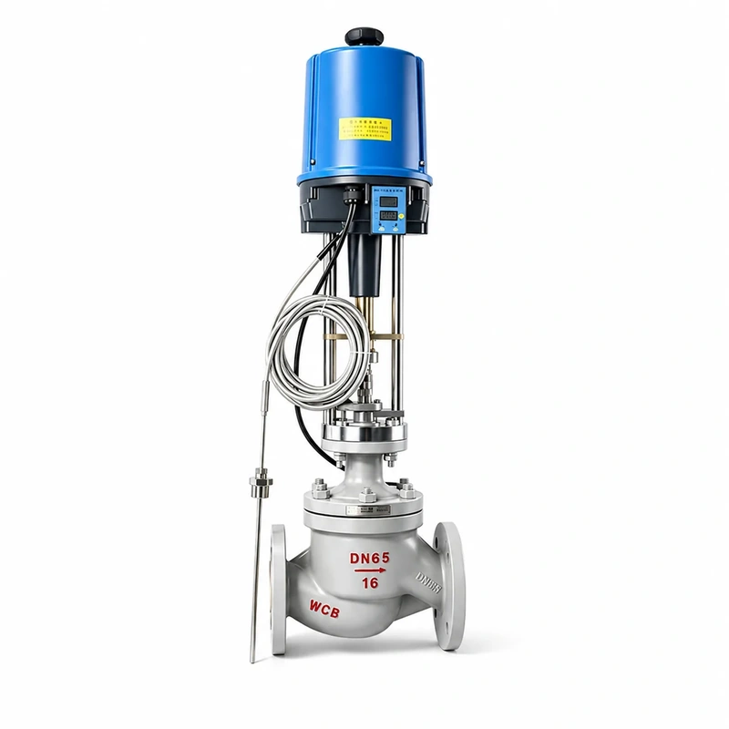
In a steam-heated heat exchanger, for example, the sensor may measure product outlet temperature while the valve adjusts steam flow. In a compressor cooling circuit, the sensor may measure coolant leaving the machine while a three-way valve divides the return flow between a cooler and a bypass. The sensing point and the valve do not have to be in the same pipe.
The name does not define the actuator, body style, or number of ports. A TCV can be self-acting, pneumatic, or electric. It can also be a two-way globe valve, a rotary control valve, or a three-way valve. The correct meaning therefore comes from the complete control function, not the product name alone.
How Does a Temperature Control Valve Work?
The valve responds to the difference between the measured temperature and the set point. The control mechanism turns that difference into stem or shaft movement, which changes heat-transfer flow until the process reaches a new balance.
Self-acting temperature regulators
A self-acting regulator combines sensing, control action, and valve movement without an external power supply. Its sensor contains a temperature-sensitive liquid, vapour charge, or thermal element. As the measured temperature changes, the sensor produces pressure, expansion, or force. An integral mechanism or capillary-connected actuator transfers that force to the valve.
In a common heating arrangement, a normally open regulator closes as the sensed temperature rises, reducing steam or hot-water flow. A cooling regulator may use the opposite action and open further as temperature rises. These are typical arrangements, not universal rules; the valve action and piping layout must match the duty.
Self-acting control is usually proportional across a temperature band. A change in process load can therefore create some offset between the set point and the final stable temperature. Sensor location, thermal lag, capillary condition, valve sizing, and the regulator’s adjustment range all affect the result.
Externally actuated temperature-control loops
An externally actuated loop separates measurement, control, and valve movement. A transmitter measures the process temperature and sends the measured value to a controller. The controller compares it with the set point and sends an output signal to a pneumatic or electric actuator. The actuator then positions the control valve.
This is the same feedback structure used in a broader control valve loop, with temperature as the controlled process variable.
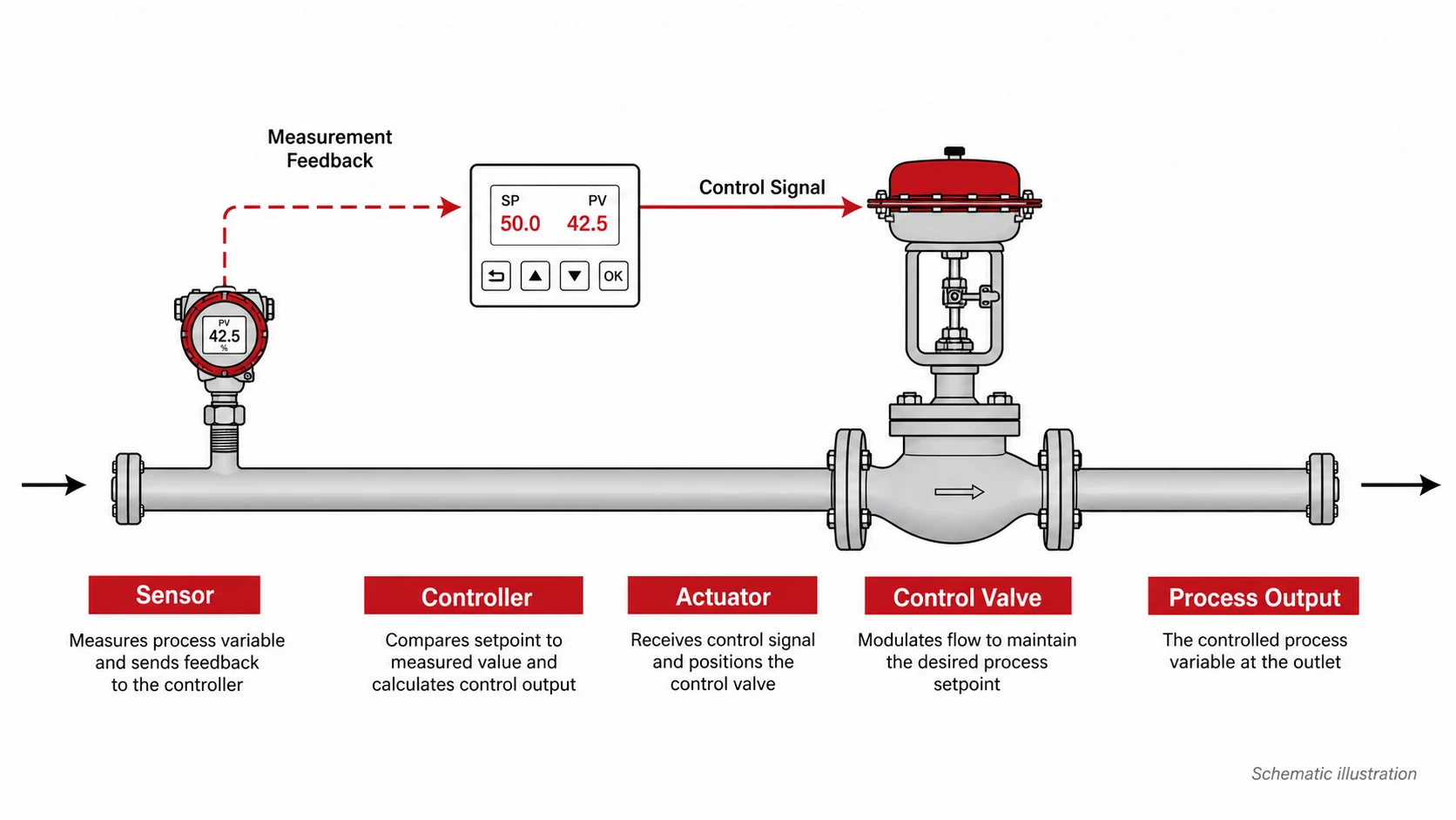
A pneumatic actuator is often used where the plant has instrument air and needs quick modulating action or a spring-defined failure position. An electric actuator can suit sites without instrument air or duties that need electrical control and position feedback. Neither type is automatically more accurate. Final temperature control also depends on the sensor, controller tuning, actuator response, valve friction, installed pressure drop, and process delay.
Temperature Control Valve Types and Flow Arrangements
Control method and flow arrangement are separate choices. A self-acting, pneumatic, or electric actuator can be paired with different valve bodies, while two-way and three-way bodies change how the process stream moves.
| Control method | External utility | Control interface | Typical fit | Main check |
|---|---|---|---|---|
| Self-acting | None | Local thermal sensor and setting mechanism | Local duty with a stable set point | Temperature band, sensor location, and load change |
| Pneumatic | Instrument air and control signal | Controller, positioner, and air actuator | Continuous industrial modulation | Air pressure, actuator force, response, and fail action |
| Electric | Electrical power and control signal | Controller and modulating electric actuator | Remote control where air is unavailable or unwanted | Voltage, speed, duty cycle, torque, and power-loss action |
The table gives an architecture boundary, not a ranking. Required response, set-point changes, alarms, interlocks, available utilities, and the safe position after a utility failure determine which method fits the process.
Two-way throttling
A two-way valve has one inlet and one outlet. It changes the flow of a heating or cooling medium through a coil, jacket, heat exchanger, or direct process line. Closing the valve reduces that branch flow, so the pump curve, bypass path, and pressure changes elsewhere in the system must be considered.
Two-way control is often simple to pipe, but the selected valve still needs usable travel at normal load. A valve that passes the design maximum at very low travel can make small stem movements produce large temperature changes.
Three-way mixing and diverting
A mixing valve combines two inlet streams into one outlet. The valve changes the proportion of hot and cold flow, or cooler and bypass flow, to control the outlet temperature. A diverting valve receives one inlet stream and divides it between two outlets, such as a cooler and a bypass line.
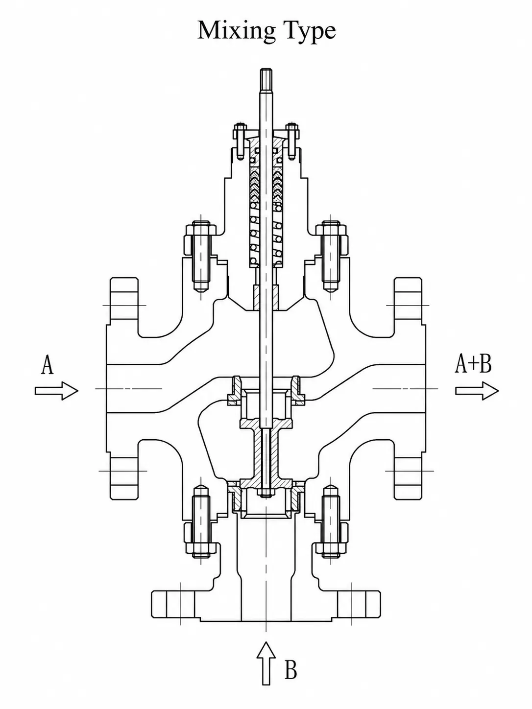
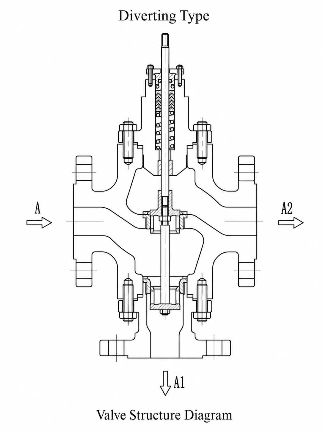
Body shape alone does not prove the permitted flow direction. Port markings, trim design, pressure conditions, and the manufacturer’s instructions must agree with the intended mixing or diverting duty. The three-way control valve flow guide explains the piping difference in more detail. After the circuit is defined, a suitable three-way mixing or diverting control valve can be matched to the flow and pressure conditions.
Where Industrial Temperature Control Valves Are Used
The same temperature set point can require a different valve when the manipulated medium, load pattern, or thermal circuit changes. Application names help only when they show what the valve is controlling.
Steam and hot-water heating
In a heat exchanger, jacketed vessel, dryer, or heating coil, the sensor often measures the product or secondary-fluid outlet temperature while a two-way valve changes steam or hot-water flow. The required valve action depends on whether increasing valve travel adds or removes heat.
Steam service also makes shut-off leakage important. A small leak through a closed seat can continue adding heat after the controller has called for closure. Available steam pressure, condensate removal, exchanger condition, and process delay can also limit temperature response even when the valve follows its command.
Cooling water for engines, compressors, and equipment
A two-way cooling valve may open as equipment outlet temperature rises, allowing more coolant through the jacket or cooler. A three-way valve can instead direct return flow through a cooler or around a bypass while keeping circulation through the equipment.
Cooling-water quality changes the valve requirement. Rust, scale, and suspended solids can block strainers, sensor pockets, or narrow trim passages. Raw-water service may need more tolerant flow passages and corrosion-resistant materials than a clean closed circuit.
Thermal-oil, lubrication, and hydraulic circuits
Three-way valves are often used to route oil through a cooler or around a bypass. Cold oil can bypass the cooler during start-up, then shift towards the cooler as temperature rises. A mixing arrangement may be used when the equipment needs a controlled supply temperature.
Oil viscosity can change sharply between cold start-up and normal operation. That change affects pressure loss and valve travel, so the circuit must be checked at both conditions. Packing, seats, and gaskets must also remain suitable at the highest operating and upset temperatures.
How to Select a Temperature Control Valve
Pipe size and temperature set point are not enough to select a TCV. The valve must control the required heat-transfer flow across the real load range while its body, trim, actuator, and sensing system remain within their operating limits.
Define the control duty, sensing point, and action
Start with the temperature that must be controlled and the stream the valve will change. A heat exchanger may measure product outlet temperature while throttling steam. A compressor circuit may measure coolant leaving the machine while diverting oil or water through a cooler. The same set point can therefore require different valve actions and piping arrangements.
A self-acting regulator may fit a stable local duty with no plant utilities. A process that needs remote set-point changes, alarms, interlocks, or close coordination with other equipment may need an external transmitter and controller. The sensor must represent the true controlled temperature without long delay from poor immersion, stagnant pockets, or a slow thermowell.
Size for minimum, normal, and maximum load
Valve sizing uses the medium, flow rate, inlet pressure, outlet pressure, and temperature at the expected operating points. Cv or Kv must be checked across minimum, normal, and maximum load because a valve sized only for peak flow may spend most of its life close to the seat.
An oversized valve can pass normal heat-transfer flow at low travel. Small movements then cause large changes in heating or cooling rate, which can make the temperature hunt and increase seat wear. An undersized valve may stay fully open and still fail to reach the set point during peak demand.
The catalogue flow characteristic also changes after the valve is installed in a piping system with a varying pressure drop. The control valve sizing guide explains the required inputs and installed-performance checks. When a formal sizing calculation is needed, IEC 60534-2-1 provides equations for compressible and incompressible flow through industrial control valves within its stated scope.
Match the body, trim, and sealing parts to the medium
A globe control valve is a common choice when stable throttling, a defined flow characteristic, and shut-off performance matter. Characterised ball, butterfly, and other rotary designs may fit larger pipe sizes, lower pressure-drop systems, or plant layout limits. A three-way body must be designed and sized for its intended mixing or diverting path.
Steam requires compressible-flow checks for velocity, noise, and possible choking. Water and other liquids may cavitate or flash when local pressure falls near vapour pressure. Dirty cooling water can block narrow passages, while cold viscous oil can create much more pressure loss than hot oil. These conditions change the trim form, guiding, passage size, and material requirements.
The body pressure-temperature rating is only one limit. Seats, packing, gaskets, trim, actuator parts, and accessories must also tolerate normal, start-up, and upset temperatures. Higher-temperature duty may require metal seating, graphite-based packing or gaskets, and an extension bonnet, but the final construction depends on the actual temperature and leakage requirement.
Seat leakage should be set by its thermal effect. Steam leaking through a closed valve may continue heating a vessel, while leakage across a closed three-way port may prevent the circuit from reaching its intended supply temperature.
Check actuator demand and failure position
The actuator must provide enough thrust or torque at the maximum differential pressure and required shut-off condition. Pneumatic selection must account for available air pressure, spring range, and positioner action. Electric selection must account for supply voltage, operating speed, modulation duty cycle, and the required response after power loss. The control valve actuator selection guide covers these differences.
Failure position follows the process consequence. A steam-heating valve is often arranged to fail closed so heat input stops after loss of air or power. A cooling-water valve may need to fail open, while freeze protection or minimum-circulation needs can lead to another choice. Normal control action and emergency failure position are separate decisions.
Common Temperature-Control Problems and Maintenance Checks
A temperature deviation does not prove that the valve is faulty. The sensor, controller, actuator, piping circuit, utility supply, and heat exchanger can create similar symptoms. Compare measured temperature, controller output, and actual valve travel before removing the valve.
| Observed symptom | Likely branches | Checks that separate them |
|---|---|---|
| Slow temperature response | Sensor lag, damaged capillary, slow actuator, or normal process delay | Sensor immersion, thermowell contact, capillary condition, actuator speed, and exchanger response |
| Temperature hunts around the set point | Oversized valve, poor tuning, stiction, or sensor location | Normal valve travel, output trend, position feedback, friction, and process delay |
| Process cannot reach the set point | Low utility pressure, limited Cv, fouling, blockage, wrong action, or short actuator travel | Available pressure, full stroke, flow rate, strainer condition, and heat-transfer capacity |
| Temperature keeps rising after closure | Seat leakage, debris, incomplete shut-off, or stored heat | Commanded and actual travel, shut-off force, downstream leakage, and residual thermal lag |
| Valve is noisy or vibrates | High pressure drop, cavitation, choked flow, unstable low travel, or loose support | Inlet and outlet pressure, flow, valve opening, trim condition, and pipe support |
If controller output changes but valve position stays flat, check the signal, air or power supply, positioner, actuator, and mechanical movement. If the valve follows its command but temperature changes little, check utility pressure or flow, exchanger fouling, bypass leakage, and sensor location. The broader control valve troubleshooting guide covers these signal-to-travel checks.
Routine checks should answer one question: can the sensing and valve system still produce the movement and heat-transfer change required by the process?
- Sensor and thermowell: check location, immersion, damage, deposits, and reference accuracy.
- Capillary and wiring: check for crushing, sharp bends, loose terminals, and heat damage.
- Strainers and flow paths: remove restrictions that limit steam, water, or oil flow.
- Valve and actuator travel: confirm smooth movement from command to actual position.
- Packing and seats: check external leakage, shut-off leakage, friction, and temperature suitability.
Internal inspection must follow the plant’s isolation, cooling, draining, and depressurisation procedures. Controller tuning should be changed only after mechanical sticking, poor sensor placement, and valve sizing have been checked.
Conclusion
A temperature control valve works well only when its control method and flow path match the thermal duty. Choose the sensing and actuation method first, then check installed flow, pressure drop, materials, sealing parts, actuator demand, and failure position across the operating range. Suitable configurations can then be compared within MacoTango’s industrial control valve range.